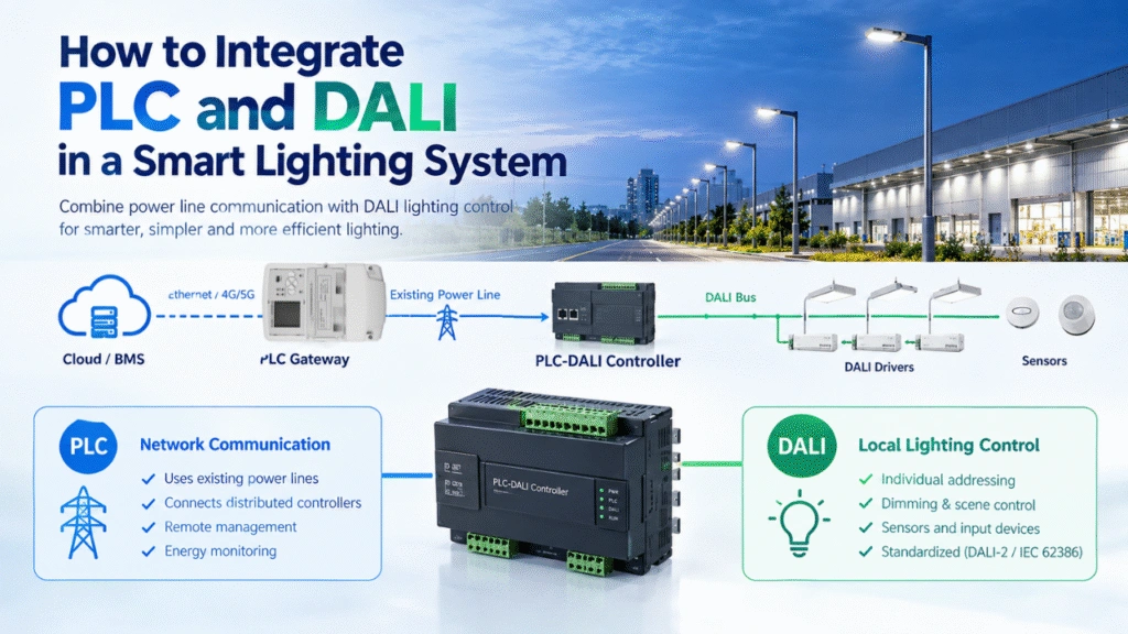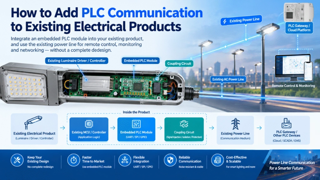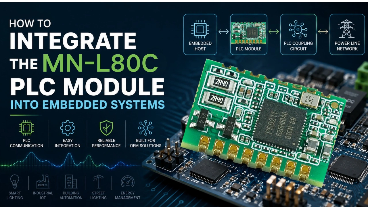
Integrando un Módulo de comunicación PLC en un sistema embebido permite a los fabricantes y desarrolladores de productos añadir Comunicación por Línea Eléctrica (PLC) sin diseñar toda la capa de comunicación del PLC desde cero. El Módulo PLC MN-L80C está diseñado para aplicaciones embebidas donde los datos de comunicación deben transmitirse a través de líneas eléctricas existentes.
Esta guía explica cómo integrar el módulo PLC MN-L80C en un sistema embebido, incluyendo arquitectura de hardware, comunicación host-controlador, conexión por línea eléctrica, consideraciones de diseño de PCB, integración de software, pruebas y problemas comunes de integración.
¿Qué es el módulo PLC MN-L80C?
El MN-L80C es un sistema embebido Módulo de Comunicación por Línea Eléctrica (PLC) diseñada para proporcionar capacidades de comunicación PLC para equipos electrónicos e industriales. Si eres nuevo aquí, primero puedes ver nuestro artículo Módulo PLC vs chipset PLC: Diferencias clave explicadas.
En lugar de añadir un cable de comunicación separado, un módulo PLC permite que dispositivos compatibles intercambien datos a través de la infraestructura de línea eléctrica existente.
Para aplicaciones OEM, el MN-L80C puede integrarse en una PCB anfitriona junto con un microcontrolador, fuente de alimentación, sensores, controladores u otros componentes electrónicos de control.
Un sistema típico de PLC embebido incluye:
- Microcontrolador o procesador anfitrión
- Módulo de comunicación PLC MN-L80C
- Fuente de alimentación aislada o diseñada adecuadamente
- Circuito de acoplamiento y protección de líneas eléctricas
- Sensores, actuadores o dispositivos de control
- Software embebido y protocolo de comunicación
- Conexión opcional de pasarela o nube
El módulo PLC gestiona la función de comunicación por línea eléctrica mientras que el MCU anfitrión gestiona la lógica de la aplicación.
¿Por qué integrar un módulo PLC en un sistema embebido?
Para muchas aplicaciones industriales y de dispositivos inteligentes, añadir otro cable de comunicación puede aumentar la complejidad y el coste de la instalación.
El PLC ofrece una alternativa utilizando el cableado eléctrico existente como medio de comunicación.
Integrar el MN-L80C en un producto embebido puede ofrecer varias ventajas:
Utilizar líneas eléctricas existentes
Los datos de comunicación pueden compartir la infraestructura existente de línea eléctrica, reduciendo la necesidad de cableado de comunicación dedicado.
Simplificar el desarrollo de productos OEM
El módulo PLC proporciona una interfaz de comunicación dedicada, permitiendo que el equipo de ingeniería del OEM se centre en el controlador de aplicaciones y la funcionalidad del producto.
Soporte para dispositivos distribuidos
El PLC es adecuado para aplicaciones donde múltiples dispositivos están distribuidos a lo largo de la misma red eléctrica.
Ejemplos incluyen:
- Iluminación inteligente
- Iluminación industrial
- Automatización de edificios
- Industrial IoT
- Alumbrado público
- Gestión energética
- Monitorización de equipos eléctricos
- Sistemas de control embebidos
Habilitar hardware personalizado
Un módulo PLC embebido puede integrarse directamente en la PCB del cliente y personalizarse según los requisitos mecánicos, eléctricos y de comunicación de la aplicación.
Arquitectura típica de sistemas embebidos MN-L80C
Una arquitectura básica de PLC embebido puede dividirse en tres secciones:
Sistema Host → Módulo PLC MN-L80C → Línea de Alimentación
El MCU anfitrión controla la aplicación. El MN-L80C gestiona la comunicación con PLC, mientras que la línea eléctrica proporciona el camino físico de comunicación.
Una arquitectura simplificada es:
 Sistema anfitrión embebido
                       │
                       │ Interfaz de anfitrión
                       ▼
              ┌──────────────────┐
              │ PLC MN-L80C │
              │ Módulo │
              └────────┬─────────┘
                       │
                       │ Señal PLC
                       ▼
             Acoplamiento por línea eléctrica
                       │
                       ▼
                 Línea eléctrica de corriente alterna
                       │
          ┌────────────┴────────────┐
          ▼                         ▼
     PLC Dispositivo A PLC Dispositivo B
En una aplicación de iluminación inteligente, por ejemplo, el MCU anfitrión puede procesar la información de los sensores y los comandos de iluminación mientras el MN-L80C transmite los datos requeridos a través de la línea eléctrica.
Paso 1: Definir los requisitos del sistema embebido
Antes de diseñar la PCB, define los requisitos de comunicación y aplicación.
Parámetros importantes incluyen:
- MCU o procesador anfitrión
- Interfaz de comunicación del host
- Protocolo de comunicación PLC(Normas de comunicación por línea eléctrica IEEE)
- Voltaje y frecuencia en la línea eléctrica
- Distancia de comunicación requerida
- Número de nodos PLC
- Requisitos de tasa de datos
- Topología de la red
- Condiciones medioambientales
- Requisitos EMC/EMI
- Requisitos de aislamiento
- Dimensiones de la placa de circuito circuito (PCB)
- Temperatura de funcionamiento
- Certificaciones requeridas
El módulo PLC debe seleccionarse según la arquitectura completa del sistema y no solo los requisitos de comunicación.
Por ejemplo, un controlador inteligente para farolas puede tener requisitos muy diferentes a los de un nodo sensor industrial o de un controlador de iluminación interior.
Paso 2: Conecta el MN-L80C al MCU del Host
El MCU anfitrión es responsable de la capa de aplicación, mientras que el módulo PLC proporciona comunicación a través de la línea de alimentación. UART vs SPI para módulos PLC: Guía, Velocidad, Coste e Integración Este artículo te ayudará a debatir sobre la interfaz host-interface.
La interfaz del host debe diseñarse según las especificaciones eléctricas y de comunicación del MN-L80C.
Una arquitectura típica es:
 MCU anfitrión
           │
           │ Interfaz de datos / control
           ▼
      ┌───────────┐
      │ MN-L80C │
      │ Módulo PLC│
      └─────┬─────┘
            │
            │ PLC
            ▼
       Red eléctrica
Durante la integración, verifica:
- Niveles de voltaje de interfaz
- Dirección de la señal
- Temporización de la comunicación
- Velocidad de baud o configuración de interfaz
- Comportamiento de reinicio
- Secuencia de encendido
- Señales de estado del módulo
- Formato de paquete
- Gestión de errores
La implementación exacta de la interfaz host debe seguir la documentación y especificaciones de integración de hardware más recientes del MN-L80C.
Paso 3: Diseña la fuente de alimentación
La alimentación estable es fundamental para la comunicación con PLC embebida. Necesitas mantener limpio el entorno PLC, este artículo Guía de solución de problemas de ruido de señal de PLC: Causas y soluciones Te ayudará a entenderlo mejor.
El MN-L80C debe recibir un suministro limpio y adecuadamente regulado del sistema anfitrión.
El diseño de la fuente de alimentación debe considerar:
- Rango de tensión de entrada
- Selección del regulador
- Capacidad actual
- Ondulación de tensión
- Respuesta transitoria
- Condensadores de desacoplamiento
- Rendimiento en EMC
- Protección contra sobretensiones
Coloca los condensadores de derivación y desacoplamiento apropiados cerca de los pines de alimentación del módulo.
Para aplicaciones industriales y exteriores, la fuente de alimentación también debe evaluarse frente a transitorios eléctricos y ruidos ambientales que puedan existir en la red eléctrica.
Paso 4: Diseña la interfaz PLC Power-Line
La señal PLC debe acoplarse a la línea eléctrica sin interferir con la función normal de entrega de potencia. Antes de empezar, por favor consulta nuestro artículo ¿Qué es la Comunicación por Línea Eléctrica (PLC)? Guía completa Para que te hagas una idea.
Esta parte del circuito es especialmente importante porque la línea eléctrica puede contener:
- Ruido de conmutación
- Ruido del motor
- Ruido de la fuente de alimentación
- Interferencia armónica
- Transitorios de carga
- EMI de otros equipos
Por tanto, la interfaz PLC debe diseñarse según el circuito de referencia MN-L80C y las especificaciones recomendadas de componentes.
Un concepto simplificado es:
 Módulo PLC MN-L80C
                │
                ▼
       Circuito de acoplamiento PLC
                │
       Protección / Filtrado
                │
                ▼
           Línea eléctrica
No trates la interfaz PLC como una simple conexión de señal digital. La red de acoplamiento y la disposición de la PCB pueden tener un efecto significativo en el rendimiento de la comunicación.
Paso 5: Diseña cuidadosamente la disposición de la PCB
La disposición de las PCB es una de las partes más importantes para integrar un módulo PLC.
Un mal diseño puede aumentar el ruido, reducir el rendimiento de la comunicación y crear problemas de EMC incluso cuando el esquema es correcto.
Mantén las conexiones críticas cortas
Mantén los caminos de señal de los PLC de alta frecuencia lo más cortos posible.
Evita bucles innecesarios o largas pistas entre el módulo y el circuito de acoplamiento.
Circuitos ruidosos separados
Mantén los circuitos relacionados con PLC alejados de fuentes de ruido importantes como:
- Fuentes de alimentación conmutadas
- MOSFETs de alta corriente
- Conductores de motor
- Relevos
- Transductores LED de alta potencia
- Interfaces digitales rápidas
Sigue la Estrategia de Conexión a Tierra Recomendada
La estrategia de puesta a tierra debe seguir el diseño de referencia MN-L80C y los requisitos de aislamiento del producto final.
No asumas que un enfoque genérico de puesta a tierra por PCB es apropiado para toda implementación de PLC.
Considera el creepage y el despeje
Cuando el sistema embebido se conecta directamente al voltaje de red, los requisitos de desplazamiento y liberación de la PCB se vuelven especialmente importantes.
La PCB final debe revisarse conforme a los estándares de seguridad aplicables para el mercado objetivo y la categoría de producto. Normas IEC Para equipos eléctricos y electrónicos es útil para tu referencia laboral.
Paso 6: Integrar el software de comunicación PLC
Una vez conectado el hardware, el MCU anfitrión necesita un firmware capaz de comunicarse con el MN-L80C.
El software embebido suele contener varias capas:
Software de aplicación
        │
        ▼
Protocolo de Comunicación PLC
        │
        ▼
Controlador de interfaz de host MN-L80C
        │
        ▼
Módulo PLC MN-L80C
        │
        ▼
Red de Línea Eléctrica
El firmware del host puede ser responsable de:
- Inicialización del módulo PLC
- Envío de comandos
- Recepción de datos PLC
- Paquetes de análisis analizable
- Gestión de errores de comunicación
- Gestión de direcciones de dispositivos
- Implementación de protocolos de aplicación
- Estado del módulo de monitorización
- Recuperación tras fallos de comunicación
Para un controlador de iluminación inteligente, la aplicación puede enviar comandos como:
- Encienda/apaga la luz
- Ajustar brillo
- Leer estado del dispositivo
- Leer información sobre fallos
- Ejecutar el control programado
- Informa sobre los datos de los sensores
El módulo PLC proporciona la ruta de comunicación mientras que el firmware de la aplicación determina el significado de los datos.
Paso 7: Definir el protocolo de comunicación
El módulo PLC debe integrarse en una arquitectura de comunicación claramente definida.
Un mensaje típico puede contener:
┌────────┬────────┬──────────┬────────┬─────────┐
│ Cabecera │ Dirección│ Comando │ Datos │ Suma de comprobación│
└────────┴────────┴──────────┴────────┴─────────┘
La estructura real del paquete depende del protocolo del sistema.
Para un producto OEM, es útil definir:
- Dirección del dispositivo
- Tipo de mando
- Longitud de la carga útil
- Formato de datos
- Número de secuencia
- Código de error
- CRC/suma de comprobación
- Tiempo muerto
- Mecanismo de reintento
Un protocolo bien definido facilita la resolución de problemas de comunicación durante el desarrollo y el despliegue en campo.
Paso 8: Prueba la comunicación del PLC en el banco
Antes de integrar el producto completo, prueba el MN-L80C en un entorno controlado. Calculadora de Distancia de Comunicación PLC | Estima el rango de la red PLC Este artículo te ayudará a saber cómo hacerlo.
Una configuración básica de pruebas puede incluir:
PC / Herramienta de depuración
       │
       ▼
   MCU anfitrión
       │
       ▼
    MN-80C
       │
       ▼
 Red de Pruebas de Línea Eléctrica
       │
       ▼
 Segundo nodo PLC
Empieza con pruebas básicas de comunicación.
Prueba 1: Inicialización del módulo
Verifica que el MCU del anfitrión pueda inicializar y comunicarse con el MN-L80C.
Prueba 2: Transmisión de datos
Envía paquetes conocidos entre dos nodos PLC y verifica que los datos recibidos coincidan con los datos transmitidos.
Prueba 3: Distancia de comunicación
Prueba el sistema con diferentes longitudes de cable y condiciones eléctricas.
Prueba 4: Prueba de ruido
Introduce cargas eléctricas representativas y observa si aumentan las pérdidas de paquetes, la retransmisión o los errores de comunicación.
Prueba 5: Pruebas de larga duración
Mantened una comunicación continua durante varias horas o días para identificar problemas intermitentes.
Paso 9: Prueba bajo condiciones reales de aplicación
Las pruebas en laboratorio por sí solas no son suficientes para muchas aplicaciones industriales de PLC.
El sistema final debe probarse en condiciones similares a la instalación real.
Por ejemplo, un controlador de iluminación inteligente debe evaluarse con:
- Drivers LED reales
- Cargas reales de iluminación
- Múltiples nodos PLC
- Líneas eléctricas largas
- Cargas de conmutación
- Condiciones eléctricas exteriores cuando sea aplicable
- Tamaño máximo esperado de la red
El objetivo es determinar si la comunicación con PLC permanece estable cuando la red eléctrica contiene el mismo ruido y cargas que se encuentran en el campo.
Problemas comunes de integración MN-L80C
Problema 1: La comunicación con PLC es inestable
Las posibles causas incluyen:
- Ruido eléctrico excesivo
- Diseño deficiente del circuito de acoplamiento
- Selección incorrecta de componentes
- Problemas con la disposición de las PCB
- Filtrado de potencia insuficiente
- Condiciones incompatibles de la línea eléctrica
Empieza comprobando la fuente de alimentación y el circuito de acoplamiento del PLC antes de cambiar el software de la aplicación.
Problema 2: El MCU del anfitrión no puede comunicarse con el módulo
Comprobar:
- Suministro eléctrico
- Cableado de interfaz
- Niveles lógicos
- Señal de reinicio
- Configuración de la interfaz
- Inicialización del firmware
- Temporización de la comunicación
Un analizador lógico puede ser útil para comprobar las señales de comunicación del lado del host.
Problema 3: La comunicación funciona en el laboratorio pero fracasa en el campo
Esto suele indicar que el entorno del campo tiene características eléctricas significativamente diferentes.
Investiga:
- Longitud del cable
- Cargas eléctricas
- Equipos de conmutación
- Drivers LED
- Motores
- Fuentes de alimentación
- Fuentes de EMI
- Topología de la red
Las pruebas de campo deben reproducir el entorno eléctrico real lo más fielmente posible.
Problema 4: El rendimiento de EMC es pobre
Los sistemas PLC operan en entornos eléctricamente ruidosos, por lo que la EMC debe considerarse desde el principio del diseño de la PCB.
Reseña:
- Enrutamiento de señales
- Conexión a tierra
- Filtrado
- Blindaje cuando sea apropiado
- Distribución de la fuente de alimentación
- Colocación de nodos de conmutación
- Caminos de alta corriente
- Diseño de acoplamiento PLC
Integración MN-L80C para productos OEM
Para los fabricantes OEM, el módulo PLC debe considerarse parte de la arquitectura general del producto en lugar de un componente de comunicación independiente.
Un proceso típico de desarrollo OEM es:
Requisitos de solicitud
          ↓
Arquitectura del sistema
          ↓
Selección MN-80C
          ↓
Circuito de referencia
          ↓
Integración de PCB
          ↓
Integración de firmware
          ↓
Pruebas de comunicación
          ↓
EMC / Pruebas de seguridad
          ↓
Producción del piloto
          ↓
Producción en masa
Este enfoque ayuda a reducir el riesgo de rediseño y permite validar la función de comunicación del PLC antes de que el producto entre en producción en masa.
El MN-L80C puede ser especialmente útil cuando un OEM necesita añadir comunicación PLC a un controlador embebido existente sin rediseñar completamente el producto alrededor de una nueva arquitectura de comunicación.
Aplicaciones del módulo PLC MN-L80C
Los módulos PLC embebidos pueden utilizarse en muchas aplicaciones donde ya hay cableado de alimentación. Cómo diseñar una red de iluminación inteligente con PLC Este artículo es importante para tu árbitro de trabajo.
Las aplicaciones potenciales incluyen:
Iluminación inteligente
Los PLC pueden conectar controladores de iluminación, gateways, sensores y otros dispositivos a través del cableado eléctrico existente.
Industrial IoT
La comunicación con PLC puede conectar dispositivos industriales distribuidos donde instalar cables de comunicación adicionales resulta difícil o costoso.
Alumbrado público
Los controladores PLC integrados pueden integrarse en equipos de iluminación exterior para monitorización, programación, atenuación y gestión de fallos centralizados.
Automatización de edificios
El PLC puede proporcionar comunicación entre controladores embebidos y dispositivos eléctricos distribuidos por todo un edificio.
Gestión energética
Los dispositivos embebidos con PLC pueden intercambiar información de monitorización y control a través de redes eléctricas.
Cómo mejorar la fiabilidad de la integración de PLC MN-L80C
Para productos listos para producción, considera estas recomendaciones:
1. Comienza desde el diseño de referencia.
Utiliza la arquitectura de hardware y los componentes recomendados como punto de partida para el desarrollo de PCB.
2. Validar la fuente de alimentación con antelación.
Una fuente de alimentación estable reduce muchos problemas de comunicación y fiabilidad.
3. Presta atención a la disposición de la PCB.
Mantén controladas las rutas de señal del PLC y separa los circuitos de comunicación sensibles de las principales fuentes de ruido.
4. Prueba con cargas eléctricas realistas.
Una fuente de energía limpia de laboratorio puede no representar el entorno real del campo.
5. Recuperación de errores de diseño en el firmware.
Incluye mecanismos de tiempo de espera, reintentos, notificación de fallos y recuperación de comunicaciones.
6. Prueba múltiples configuraciones de red.
No valides solo un nodo PLC. Prueba el número esperado de dispositivos y la topología de la red.
7. Realizar pruebas EMC antes de la producción final.
Identificar los problemas de EMC a tiempo es mucho menos costoso que rediseñar un producto terminado.
MN-L80C vs. Diseñar un sistema de comunicación PLC desde cero
Para un OEM, existen dos enfoques posibles: desarrollar internamente el hardware y software de comunicación PLC, o integrar un módulo PLC existente.
El uso de un módulo PLC embebido puede reducir la complejidad del desarrollo porque la función de comunicación ya se proporciona como un módulo dedicado.
| Enfoque de Desarrollo | Integración de módulos PLC | Desarrollar un sistema PLC desde cero |
|---|---|---|
| Desarrollo de hardware | Inferior | Más alto |
| Desarrollo de comunicaciones PLC | Reducido | Significativo |
| Integración de PCB | Obligatorio | Obligatorio |
| Desarrollo de firmware | Enfoque en la aplicación | Comunicación + aplicación |
| Tiempo de desarrollo | Generalmente más corta | Generalmente más largo |
| Personalización | Alto | Muy alto |
| Recursos de ingeniería | Inferior | Más alto |
Para las empresas que desarrollan un producto habilitado con PLC por primera vez, la integración de módulos puede ser una forma práctica de acortar el ciclo de desarrollo manteniendo el control sobre el producto anfitrión.
Lista de verificación de integración de módulos PLC MN-L80C
Antes de pasar a producción, verifica lo siguiente:
- La interfaz MCU del host es compatible
- La fuente de alimentación del módulo está dentro de las especificaciones
- Los componentes de desacoplamiento están correctamente colocados
- El circuito de acoplamiento PLC sigue el diseño de referencia
- Se cumplen los requisitos de desplazamiento y espacio de la PCB
- Se ha revisado el enrutamiento de señales PLC
- El firmware inicializa correctamente el módulo
- Se han probado los paquetes de comunicación
- Se implementan mecanismos de gestión de errores y reintentos
- Se ha probado la distancia de comunicación
- Se ha probado el funcionamiento entre múltiples nodos
- Se han probado cargas eléctricas reales
- Se ha evaluado el rendimiento de EMC
- Se han completado las pruebas medioambientales
- La PCB de producción ha sido validada