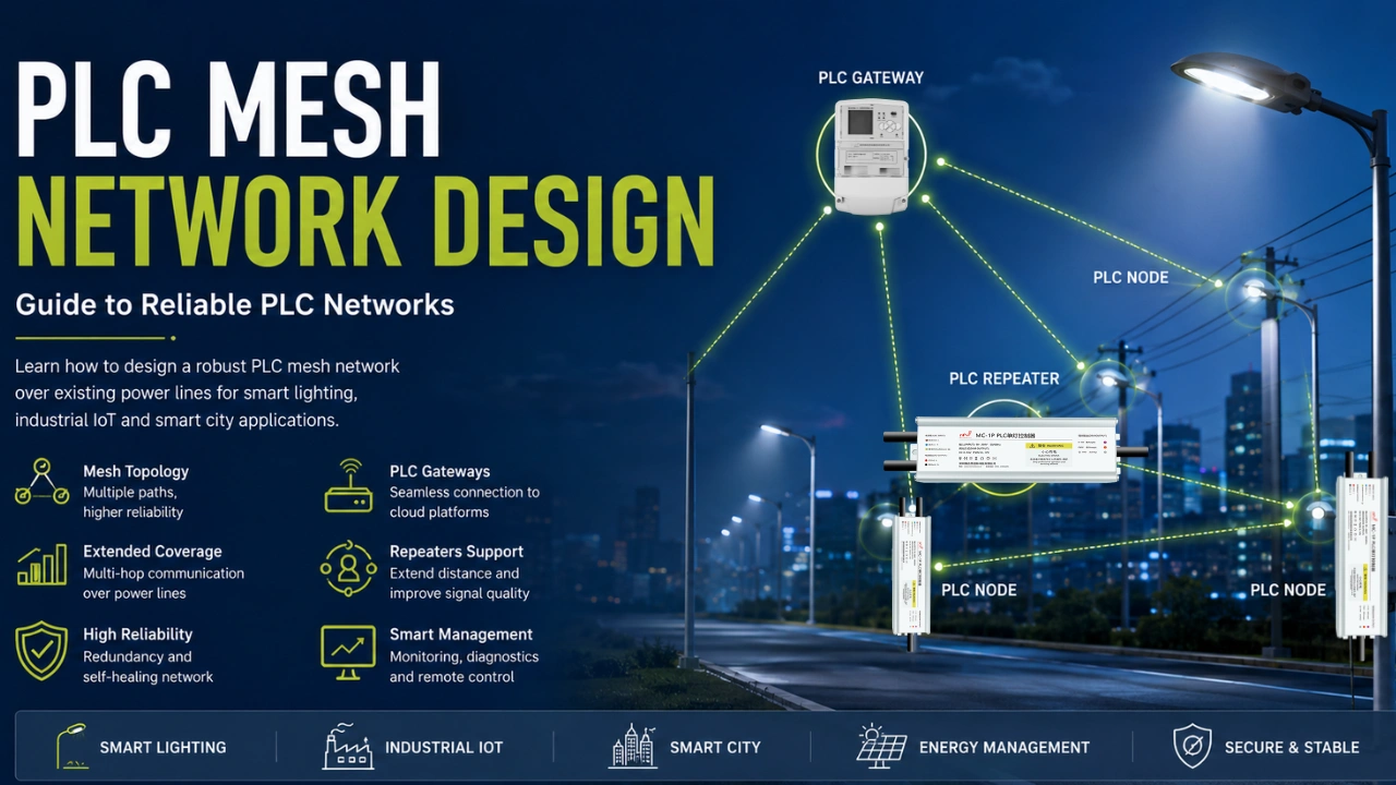
Um PLC mesh network uses existing electrical power lines to transmit data between communication nodes, allowing devices to communicate without installing dedicated communication cables. For smart lighting, industrial IoT, and other distributed applications, PLC mesh networking can provide reliable communication across large areas while reducing additional wiring infrastructure.
However, a reliable PLC mesh network requires more than simply connecting PLC devices to the same power circuit. Network topology, power-line conditions, communication distance, electrical noise, node density, gateways, and routing strategy all affect network performance.
This guide explains how to design a PLC mesh network and the key factors to consider when deploying a reliable power line communication network.
What Is a PLC Mesh Network?
Um PLC mesh network is a communication network in which multiple PLC nodes communicate through electrical power lines while using multiple possible communication paths between nodes. PLC networking technologies can be based on standardized specifications such as IEEE 1901.1, which defines a medium-frequency power line communication standard for smart grid and related applications.
Unlike a simple point-to-point PLC connection, a mesh network can allow data to travel through intermediate nodes when the direct communication path is weak or unavailable.
Por exemplo:
Gateway → PLC Node A → PLC Node B → PLC Node C
If the gateway cannot reliably communicate directly with Node C because of distance or attenuation, Node A or Node B can help forward the communication.
This multi-hop architecture can improve network coverage and reliability in large or electrically complex installations.
A typical PLC mesh network may include:
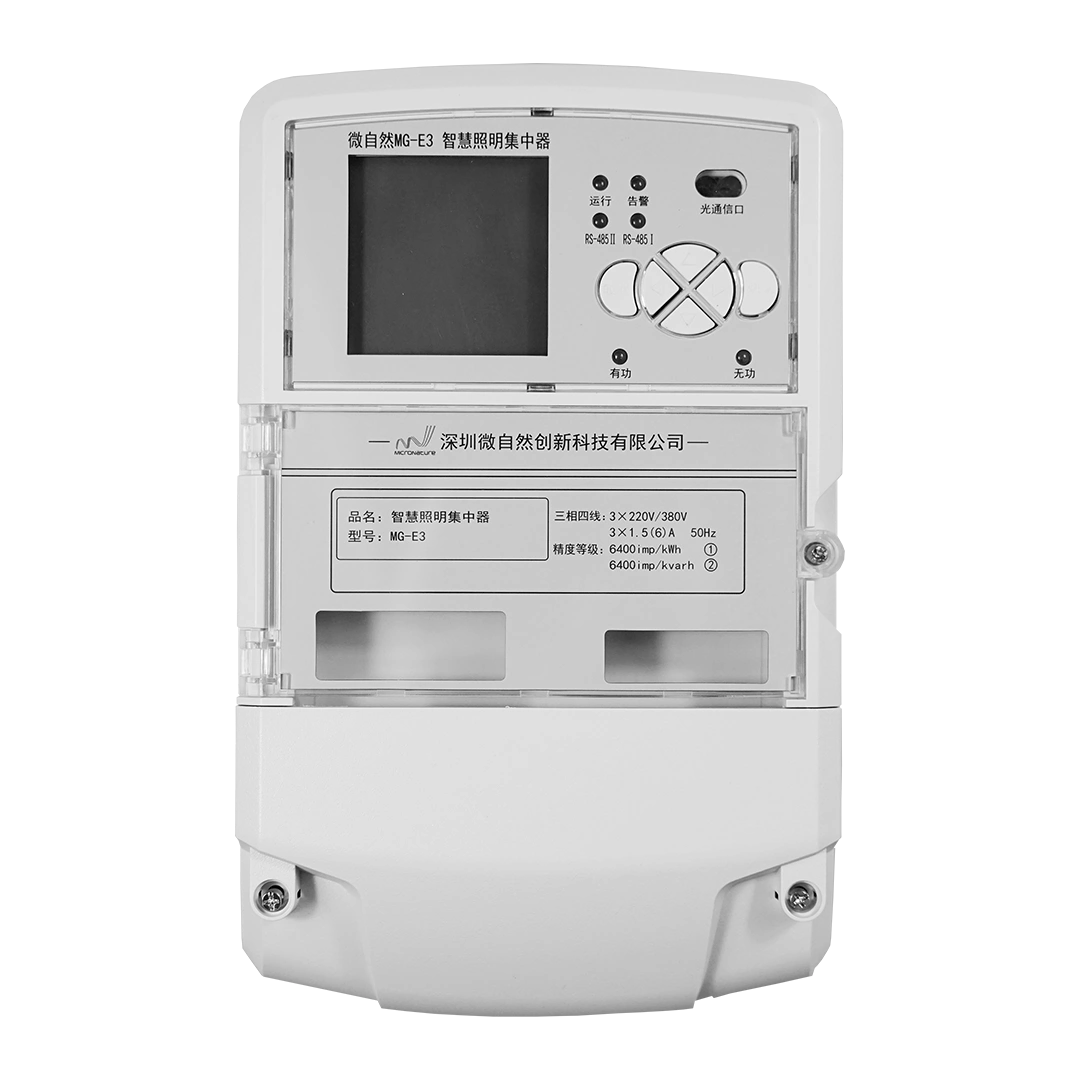
- Gateway ou concentrador PLC
- PLC communication modules
- Single-light controllers
- Repetidores PLC
- Sensores
- Smart meters or other terminal devices
- Management software or cloud platform
For smart lighting applications, the PLC network can connect a large number of street lights, tunnel lights, industrial lights, or other lighting controllers through existing power infrastructure.
How Does a PLC Mesh Network Work?
A PLC mesh network injects a modulated communication signal onto an electrical power line. PLC nodes receive the signal, decode the data, and can communicate with other nodes according to the network architecture. For a broader discussion of smart lighting architecture, see our guide on how to design a PLC smart lighting network.
A simplified architecture looks like this:
Cloud Platform / Management Software
↓
PLC Gateway
↓
Linha de Energia
↓
PLC Mesh Nodes
↙ ↓ ↘
Node A — Node B — Node C
↓
Lighting Controllers / Sensors / Devices
The gateway acts as the connection between the PLC field network and an upper-level network such as Ethernet, 4G/5G, or another IP-based communication system.
Each PLC node can communicate with nearby nodes, while the network uses available paths to deliver data to the intended destination.
The exact networking mechanism depends on the PLC technology and protocol being used.
PLC Mesh Network vs. Point-to-Point PLC
Before designing a network, it is important to understand the difference between point-to-point PLC communication and mesh networking.
| Característica | Point-to-Point PLC | PLC Mesh Network |
|---|---|---|
| Communication paths | Geralmente um | Multiple possible paths |
| Network coverage | Limited by direct link | Can extend through multiple nodes |
| Escalabilidade | More limited | Better suited to distributed networks |
| Redundancy | Baixo | Mais alto |
| Complexidade da instalação | Lower | Mais alto |
| Network planning | Relatively simple | Requires topology and routing planning |
| Large-area applications | Less suitable | Well suited |
A point-to-point connection may be sufficient when two PLC devices are close together and the power-line environment is predictable.
A mesh architecture becomes more useful when devices are distributed over a large area or when direct communication cannot reliably cover the entire network.
Key Components of a PLC Mesh Network
1. PLC Gateway
The PLC gateway is the central communication interface between the PLC field network and the management system.
Depending on the application, a gateway may use:
- Ethernet
- 4G
- 5G
- Wi-Fi
- Fibra
- Other IP communication interfaces
In smart lighting systems, the gateway can receive commands from a cloud platform and distribute them to individual lighting controllers through the PLC network.
It can also collect operating data, alarms, energy information, and device status from field nodes.
2. PLC Communication Nodes
PLC nodes are the devices that participate in the field network.
A PLC node may be integrated into:
- Controladores de postes de luz
- Industrial lighting controllers
- Sistemas de iluminação em túneis
- Medidores inteligentes
- Sensores
- Embedded control equipment
- Other IoT devices
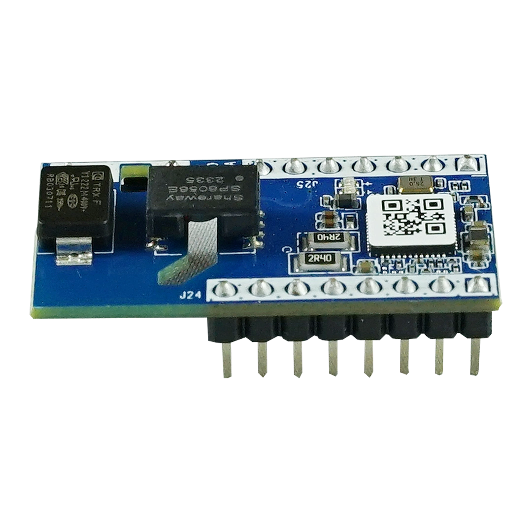
For OEM applications, a Módulo de comunicação por linha de energia can provide the PLC communication function inside the customer’s equipment.
3. PLC Repeaters
A PLC repeater can help extend communication coverage when the signal between two network areas is insufficient.
Repeaters can be useful when:
- A distância de comunicação é longa
- Cable attenuation is high
- Electrical equipment creates interference
- The power network contains multiple sections
- Direct communication between nodes is unreliable
However, repeaters should not simply be added everywhere. Proper network testing should determine where additional communication support is actually needed.
4. Power Distribution Network
The electrical distribution network is also part of the communication environment.
The physical characteristics of the power network can strongly influence PLC communication performance.
Important factors include:
- Comprimento do cabo
- Tipo de cabo
- Cable impedance
- Transformer structure
- Branches
- Circuit segmentation
- Electrical loads
- Phase configuration
- Coupling conditions
For this reason, PLC network design should consider both electrical distribution e communication topology.
How to Design a PLC Mesh Network
A reliable PLC mesh network should be designed systematically rather than by simply installing nodes and testing after deployment.
Step 1: Define the Application Requirements
Start by defining what the network needs to accomplish.
Considere:
- Number of PLC nodes
- Required communication distance
- Data volume
- Response time
- Disponibilidade da rede
- Required redundancy
- Number of gateways
- Monitoring requirements
- Condições ambientais
For a smart street lighting project, for example, the network may need to support individual lamp control, dimming, energy monitoring, fault alarms, scheduling, and sensor data.
Step 2: Map the Power Distribution Network
Create a detailed map of the electrical infrastructure before deciding on the communication topology.
Identify:
- Distribution cabinets
- Transformadores
- Feeder lines
- Circuitos ramificados
- Lighting poles
- Electrical equipment
- Long cable sections
- Potential communication barriers
This map provides the physical foundation for the PLC network design.
Step 3: Determine PLC Node Locations
PLC node placement is one of the most important parts of mesh network design.
Nodes should be positioned so that neighboring nodes have sufficient communication quality.
Avoid designing the network solely according to geographical distance. Two devices that are physically close may have poor PLC communication if they are separated by unfavorable electrical infrastructure.
Instead, evaluate the actual power-line path and expected signal conditions.
Step 4: Evaluate PLC Signal Quality
Signal quality should be evaluated under realistic operating conditions.
Important measurements include:
- Received signal strength
- Signal-to-noise ratio
- Packet error rate
- Communication success rate
- Nível de ruído
- Link stability
- Communication latency
Testing should ideally include different operating conditions because electrical loads can change during the day.
For example, a network that performs well during commissioning may experience additional noise when industrial equipment, LED drivers, motors, or other electrical loads are operating.
Step 5: Design the Mesh Topology
Once node locations and signal conditions are understood, define the communication topology.
A practical PLC mesh network may use:
Gateway → Primary PLC Nodes → Secondary PLC Nodes → End Devices
The design should provide sufficient connectivity between neighboring nodes while avoiding unnecessary communication hops.
A good mesh topology balances:
- Cobertura
- Redundancy
- Number of hops
- Communication latency
- Network capacity
- Custo de instalação
Step 6: Plan Network Capacity
Network capacity becomes increasingly important as the number of nodes grows. For a more detailed approach to estimating network capacity, see our PLC network capacity calculation guide.
Do not calculate capacity only from the PLC PHY data rate. Actual application throughput depends on factors such as:
- Protocol overhead
- Packet size
- Retransmissions
- Roteamento
- Number of active devices
- Communication frequency
- Network contention
- Channel conditions
For smart lighting, a network with hundreds of lamps may generate relatively low data traffic under normal operation, but simultaneous commands, status reporting, fault alarms, and sensor data can increase network activity.
Therefore, capacity planning should consider the expected communication pattern rather than only the theoretical maximum data rate.
Step 7: Consider Electrical Noise
Electrical noise is one of the major factors affecting PLC communication.
Potential noise sources include:
- Drivers de LED
- Fontes de alimentação comutadas
- Variable-frequency drives
- Motores
- Inversores
- Carregadores de veículos elétricos
- Equipamentos industriais
- Solar power equipment
- Other switching electronics
A PLC network designed for a low-noise environment may require additional measures in an industrial environment.
Possible approaches include:
- Improving node placement
- Adding suitable repeaters
- Using appropriate PLC communication technology
- Filtering problematic interference sources
- Improving signal coupling
- Optimizing network routing
Step 8: Design for Redundancy
One of the main advantages of mesh networking is the possibility of having multiple communication paths.
For critical applications, avoid creating a network in which one node becomes a single communication bottleneck.
A more robust topology may provide alternative paths between different sections of the network.
If one communication link becomes unavailable, another path may allow the network to continue operating.
The required redundancy level depends on the application.
For example, municipal street lighting may require a different redundancy strategy from industrial process control or critical infrastructure monitoring.
Step 9: Commission and Test the Network
Network commissioning should verify both individual links and overall network behavior.
Os exames recomendados incluem:
- Descoberta de dispositivos
- Network registration
- Link quality testing
- Multi-hop communication testing
- Packet delivery testing
- Gateway communication testing
- Load testing
- Fault recovery testing
- Power-cycle recovery
- Long-term stability testing
Testing should also be performed under realistic electrical load conditions whenever possible.
PLC Mesh Network Design Considerations
Distância de Comunicação
PLC communication distance depends on the actual power-line environment rather than a single universal number. Engineers can also use a PLC communication distance calculator as an initial reference when evaluating network coverage.
Cable characteristics, electrical noise, impedance, network topology, and connected equipment can all affect the practical communication distance.
For this reason, published communication distance should be treated as a reference rather than a guaranteed field result.
Number of Hops
More hops can extend network coverage, but excessive hops can increase:
- Latência
- Network traffic
- Routing complexity
- Dependency on intermediate nodes
A well-designed mesh network therefore seeks a reasonable balance between coverage and hop count.
Network Density
Higher node density can provide more possible communication paths, but it can also increase network traffic.
The optimal node density depends on:
- Application traffic
- PLC protocol
- Physical network structure
- Distância de Comunicação
- Reliability requirements
Phase and Circuit Structure
Three-phase and multi-branch electrical systems require particular attention during PLC network design.
The communication signal may experience different conditions across phases, feeders, distribution cabinets, and transformers.
The network design should therefore account for the actual electrical topology instead of assuming that all connected circuits provide equivalent PLC communication conditions.
EMI and Filtering
Electromagnetic interference can reduce PLC communication reliability.
In environments with significant interference, engineers may need to identify the source and evaluate whether filtering, isolation, network redesign, or equipment changes are appropriate.
A signal isolator or EMI filter can also be considered where appropriate to suppress unwanted interference while preserving the intended PLC communication signal.
PLC Mesh Network for Smart Lighting
PLC mesh networking is particularly suitable for large-scale smart lighting applications because the existing lighting power infrastructure can also serve as the communication medium.
A typical smart lighting architecture can include:
Plataforma de Gerenciamento de Nuvem
↓
4G/5G/Ethernet PLC Gateway
↓
PLC Power Network
↓
PLC Mesh Network
↓
Individual Light Controllers
↓
LED Lights + Sensors
This architecture can support functions such as:
- Remote on/off control
- Individual lamp dimming
- Controle do grupo
- Programação
- Monitoramento energético
- Detecção de falhas
- Lamp status monitoring
- Integração com sensores
- Configuração remota
- Coleta de dados
The main advantage is that communication can be deployed over existing power infrastructure without installing a separate communication cable for every lighting point.
PLC Mesh Network for Industrial IoT
PLC mesh networking can also be applied beyond lighting.
Potential applications include:
- Iluminação industrial
- Fábricas inteligentes
- Armazéns
- Ports
- Estaleiros
- Sistemas fotovoltaicos
- Infraestrutura de recarga de VE
- Gestão de energia
- Industrial monitoring
Industrial environments can present challenging PLC communication conditions because of motors, inverters, switching equipment, and other sources of electrical noise.
Therefore, industrial PLC mesh networks should place particular emphasis on signal quality testing, EMI management, redundancy, and long-term reliability.
Common PLC Mesh Network Design Mistakes
Designing Only by Physical Distance
Physical distance does not necessarily determine PLC communication quality.
The electrical path and network structure are often more important than straight-line distance.
Ignoring Electrical Loads
A network can behave differently when large electrical loads are operating.
Commissioning tests should therefore reflect actual operating conditions.
Using Too Many Repeaters
Repeaters can improve coverage, but unnecessary repeaters can increase network complexity and traffic.
Use measurements to determine where they are needed.
Ignoring Network Capacity
A network may work well with a small number of devices but experience delays when many nodes communicate simultaneously.
Capacity planning should be performed before deployment.
Creating a Single Point of Failure
A mesh network should take advantage of alternative communication paths where application reliability requires them.
Treating Theoretical Data Rate as Actual Throughput
PLC PHY rates do not represent the actual application throughput available to every node.
Protocol overhead, retransmissions, routing, and network traffic must be considered.
How to Improve PLC Mesh Network Reliability
A reliable PLC mesh network typically combines several design practices:
1. Use appropriate PLC technology
Select a PLC solution suitable for the required data rate, distance, noise environment, and application.
2. Test the actual power network
Perform field measurements rather than relying only on theoretical calculations.
3. Optimize node placement
Ensure neighboring nodes have adequate communication quality.
4. Control electrical interference
Identify and mitigate major noise sources where necessary.
5. Avoid excessive hops
Use a topology that provides coverage without unnecessarily long routing paths.
6. Provide redundancy where required
Design alternative communication paths for critical applications.
7. Monitor the network continuously
Use gateway and cloud software to monitor device status, communication quality, and faults.
PLC Mesh Network Design Checklist
Before deployment, engineers can use the following checklist:
- Define the number of PLC nodes
- Define communication and reliability requirements
- Map the power distribution network
- Identify transformers and circuit branches
- Evaluate expected communication distances
- Identify potential EMI sources
- Plan PLC gateway locations
- Determine PLC node locations
- Evaluate signal quality
- Design communication routes
- Estimate network capacity
- Determine whether repeaters are required
- Plan redundancy for critical links
- Test the network under realistic loads
- Perform long-term stability testing
- Configure monitoring and fault management