In a power plant, the lighting system can fail as a control network long before the luminaires themselves fail. Generators, transformers, high-current equipment, long feeders, switching devices, and electrically noisy loads create conditions that ordinary commercial lighting controls rarely face. The practical answer is not simply to choose a more powerful controller. A reliable design keeps sensitive central equipment away from the harshest electrical zones, divides long communication paths into manageable segments, protects those segments against interference, and gives critical lighting a control path that does not depend entirely on communications.
A practical power plant lighting solution therefore needs more than remote switching. It needs a communication architecture that fits the plant’s electrical environment, keeps long or difficult feeder sections manageable, and allows critical lighting to remain available when communication is degraded. MicroNature’s PLC lighting approach combines gateway-based communication, local control, network segmentation, and project-specific integration to support these requirements.
Here, PLC means Power Line Communication, also described as power line carrier communication. It does not mean Programmable Logic Controller. A power plant may use both technologies in the same project, but they serve different roles. Power Line Communication carries lighting control data through the electrical wiring, while a Programmable Logic Controller may belong to the plant’s process or automation system. Keeping that distinction clear prevents confusion during design reviews, integration discussions, and procurement.
Why Power Plant Lighting Needs a Different Control Architecture
High EMI changes the communication problem
In a warehouse or office, designers can often treat the lighting communication network as a relatively predictable environment. A power plant gives them a different starting point. The same lighting feeder may run beside large motors, transformers, generator equipment, switchgear, or other high-power systems. Each section of the route may therefore present a different interference profile.
This matters because a smart lighting system depends on more than power delivery. Operators expect schedules to execute correctly, commands to reach the intended zone, fault information to return to the control room, and local devices to respond consistently. If one electrically noisy area can disturb a long communication path, a problem that begins beside one piece of equipment may become difficult to isolate.
A more useful design question is therefore not, “How far can one controller communicate?” It is, “How should we divide this feeder so that each section remains manageable?” That shift in thinking changes the architecture. Instead of building one long communication domain, engineers create controlled boundaries and distribute responsibility across the network.
Existing power lines can carry both power and control data
PLC uses existing electrical conductors to carry communication data. In suitable retrofit projects, this can reduce the need for separate dedicated communication wiring.
However, the power line is not a clean data cable: feeder length, connected loads, branching, and electrical noise still need to be considered during design.
PLC Lighting Architecture for Power Plants
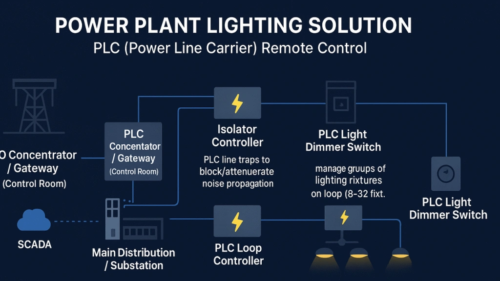
This is why the proposed power plant architecture uses several layers instead of relying on one central device. The PLC gateway handles communication with the supervisory system. Isolator controllers divide the electrical network into sections. Loop controllers organize local fixture groups. Field devices execute lighting commands near the luminaires. Filtering, surge protection, shielding, and grounding support those layers where the site requires them.
Central Gateway and Supervisory Connection
Where the plant layout allows it, the main PLC gateway can be placed in a lower-interference area such as a control room.
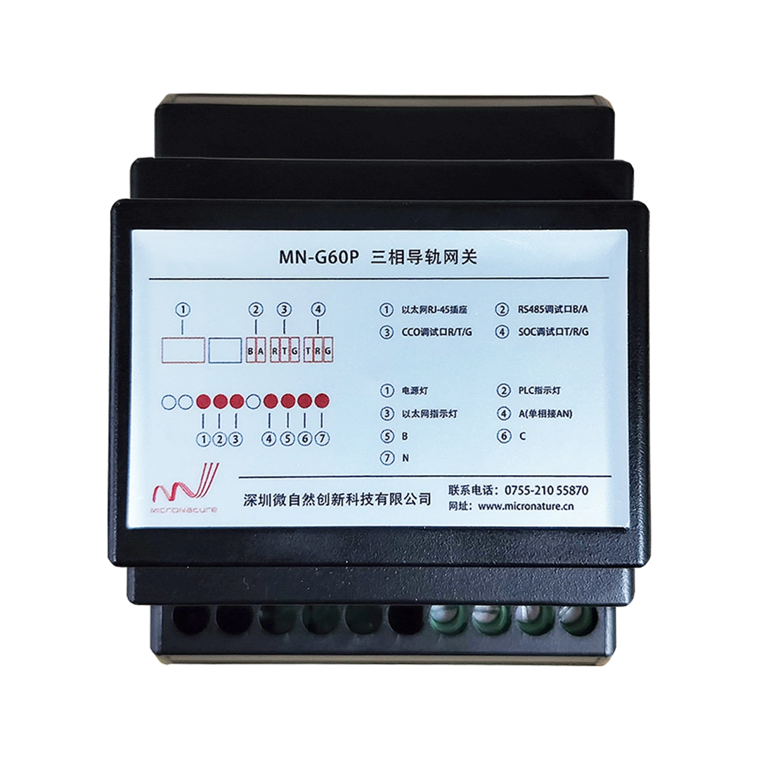
From there, the Industrial PLC Gateway can inject and receive PLC communication signals on the lighting network while connecting with the local HMI, SCADA environment, or other management software. This arrangement keeps the supervisory layer in a more controlled location and leaves field-side devices to handle local communication closer to the luminaires.
The location decision also simplifies troubleshooting. When the gateway, servers, and operator interface remain away from the strongest electromagnetic sources, engineers can separate central-system issues from field-segment issues more easily. If communication deteriorates in a turbine-hall section, the maintenance team can investigate that segment without immediately treating the gateway itself as the likely cause.
Use fiber where the supervisory backbone crosses difficult electrical areas
The lighting feeder and the supervisory backbone do not have to use the same communication medium. Where the plant architecture requires electrical isolation between the supervisory system and difficult electrical areas, fiber can be considered for the higher-level network connection. PLC can then continue to carry communication over suitable lighting power circuits.
This hybrid approach gives each medium a clear job. Fiber can provide electrical isolation for higher-level network links. PLC can reduce additional field communication wiring on the lighting side. The result is not a competition between technologies; it is a layered architecture that places each communication method where it makes engineering sense.
Segment the Lighting Network Before Interference Spreads
Isolator boundaries turn a long feeder into manageable sections
Long uninterrupted PLC domains make troubleshooting harder because disturbances have more opportunity to affect other parts of the network. Strategic segmentation addresses that problem. Isolator controllers can divide feeders near electrically difficult locations and create clearer boundaries between communication sections.
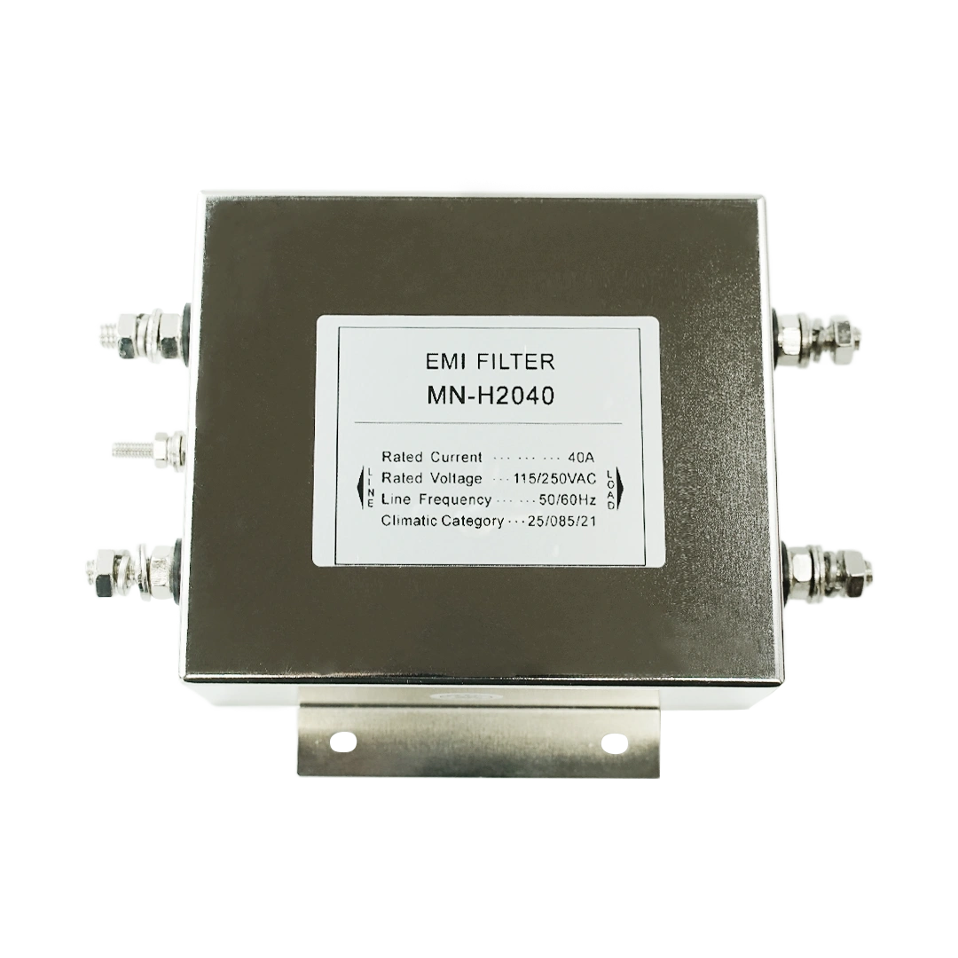
Suitable coupling filters, line traps, or other filtering components may be used where the feeder arrangement and measured interference conditions require them.
The goal is not to make one device tolerate every electrical disturbance; the goal is to stop one difficult section from becoming a lighting problem across the whole plant.
That principle is especially useful around generators, transformers, and other zones where interference conditions can differ sharply from nearby areas. Instead of asking a central controller to compensate for everything downstream, the network limits the size of each communication domain.
Loop controllers keep local lighting groups easier to control and maintain
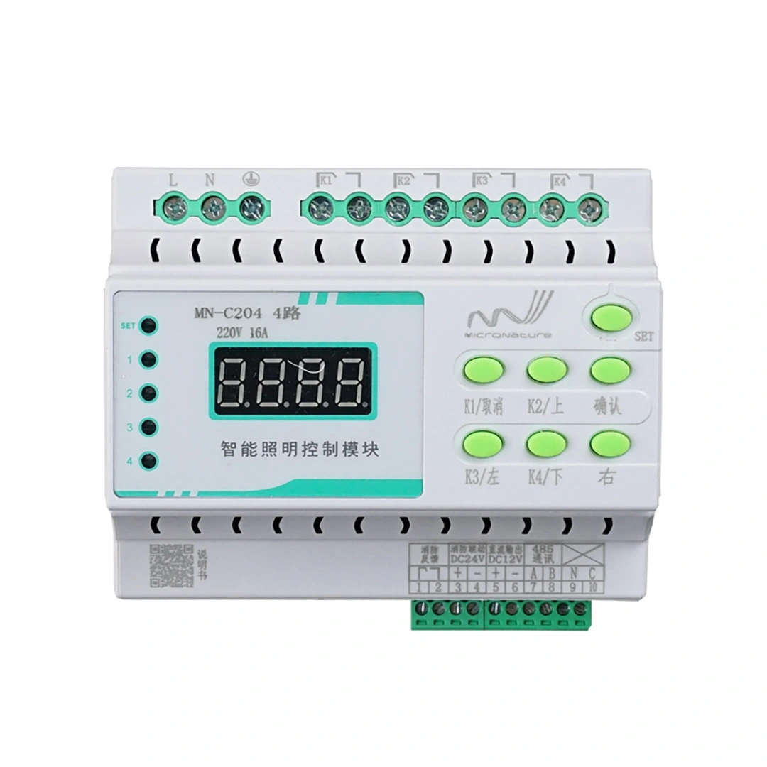
After the system creates communication boundaries, local loop controllers can organize fixtures into practical operating groups. The power plant solution concept uses PLC loop controllers to manage groups of luminaires, aggregate information, and support local schedules. Local loop controllers can organize fixtures into practical operating groups. The final number of fixtures per loop should follow the controller’s actual capacity, feeder conditions, load characteristics, and project requirements rather than a fixed number applied to every plant.
A PLC Loop Controller also gives maintenance teams a more useful troubleshooting boundary. If a group stops responding normally, technicians can narrow the investigation to a loop or segment rather than checking every luminaire connected to a large lighting network.
This local grouping becomes even more valuable when plant operating areas have different schedules. A turbine maintenance zone may need full output during planned work. A service road may follow a time schedule. A standby area may normally operate at a lower level. Local loop organization lets the control logic reflect those differences without forcing every fixture into one plant-wide operating pattern.
Match the Control Strategy to Each Power Plant Zone
Turbine and boiler halls need localized resilience
A turbine hall and a service road may belong to the same power plant, but they should not automatically share the same control design. Near large generators and other high-power equipment, the project team should first identify where communication electronics can stay farther away from strong electromagnetic fields. Moving equipment to a better location often gives a cleaner result than adding shielding after installation.
Where relocation is impossible, engineers can consider appropriate shielded enclosures, ferrite components, filtering, and local segmentation. Where field-side PLC electronics must remain close to high-field zones, the project team can evaluate suitable shielded enclosures and other EMI-mitigation measures. The actual enclosure design, grounding method, and installation position should follow site conditions and engineering verification.
Boiler halls introduce their own practical concerns. Lighting circuits may cover large areas, cross several equipment zones, and require different operating scenes for normal production and maintenance. Local control groups help keep those requirements manageable. They also reduce the amount of the network that technicians need to disturb when they service one section.
Outdoor yards and service roads make feeder distance more important
Control yards and service roads change the problem again. Here, the dominant issue may shift from proximity to large machinery toward long feeder runs, distributed luminaires, branching, outdoor exposure, and surge risk.
A long route should not automatically become one long communication segment. Engineers can place isolation points where the feeder topology, distribution panels, or electrical environment naturally divide the system. Local loop controllers can then manage groups of luminaires closer to the load.
| Plant Area | Main Control Challenge | Practical Design Response | Procurement Information Needed |
|---|---|---|---|
| Turbine Hall | Strong magnetic fields and electrical interference near major equipment | Keep central electronics remote, shorten difficult PLC segments, add isolation where required | Generator locations, feeder routes, fixture groups, equipment distances |
| Boiler Hall | Large distributed lighting area and varied maintenance conditions | Divide fixtures into local loops and define separate operating scenes | Fixture quantity, panel locations, maintenance zones, scheduling requirements |
| Control Yard | Long outdoor feeders, switching effects, and surge exposure | Use segmented communication, localized protection, and accessible field control points | Feeder lengths, branch layout, surge protection arrangement, panel locations |
| Service Roads | Distance and distributed fixtures | Group luminaires into manageable PLC loops with centralized scheduling | Pole spacing, circuit layout, control groups, required dimming scenes |
| Emergency Circuits | Lighting must remain available even when communication is degraded | Use independent hard-wired or local autonomous control where required | Emergency circuit classification, override logic, local control requirements |
This zone-by-zone approach also gives procurement teams a more reliable basis for equipment quantities. Gateway count, isolator positions, loop-controller quantity, field-control density, surge protection, and enclosure requirements should come from the electrical topology rather than from a generic bill of materials.
Build EMI Protection in Layers
Placement comes before shielding
When engineers face a high-interference environment, it is tempting to start by specifying shielded equipment everywhere. A better sequence starts with location. Keep the gateway, servers, and supervisory equipment in a lower-interference room. Then identify which field devices genuinely need to remain close to generators, transformers, or other high-field equipment.
Only after that mapping should the team decide where shielding makes sense. A field-side controller that sits in an electrically difficult area may benefit from a suitable shielded enclosure. A controller that can move several meters or into another electrical room may not need the same treatment.
This approach avoids turning customized industrial lighting solutions into unnecessarily complicated installations. Customization should solve a measurable site problem. It should not add special hardware simply because the project happens to be a power plant.
Filters, line traps, grounding, and surge protection support communication stability
Conducted interference also needs attention. Ferrite chokes and common-mode filters can help control unwanted noise on selected leads. Coupling filters and line traps can support PLC segment boundaries. Local surge protection can reduce exposure to transients at feeders, outdoor points, and field equipment.
These measures should be considered together because each addresses a different part of the electrical environment. One filter cannot compensate for poor segmentation. Shielding cannot correct a badly chosen equipment location. A strong gateway cannot solve every disturbance on a long feeder from the control room. The project becomes more robust when each layer handles a specific risk.
Grounding belongs in the same discussion. Enclosures, filters, surge protective devices, and field controllers need an installation method that fits the plant’s grounding and bonding design. Lighting-control engineering should therefore coordinate with the electrical team instead of treating communication protection as a separate low-voltage package.
The proposed power plant solution also recommends commissioning the carrier frequency and coupling or filtering arrangements according to actual site conditions. This is important because the electrical environment changes with feeder topology and connected equipment. What works on one circuit should not automatically become the setting for every other circuit.
Keep Emergency Lighting Independent of the Communication Network
Remote control should never become the only path for critical lighting
Smart control adds operational flexibility, but critical lighting needs a separate continuity strategy. If a plant requires an emergency circuit to remain available regardless of PLC communication quality, the system should not make successful data transmission a prerequisite for keeping that circuit on.
The proposed architecture therefore separates safety-critical or emergency lighting from normal dimming logic where necessary. Depending on project requirements, engineers can use independent hard-wired control, non-dimmable emergency circuits, local autonomous controllers, or redundant relays so the required lighting function remains available even when the PLC communication layer becomes degraded.
This separation also simplifies control priority. Emergency or critical overrides should take precedence over energy-saving scenes. Maintenance and full-output commands can follow. Standby schedules can sit below them. The exact logic will depend on the plant, but the hierarchy should be explicit before commissioning rather than discovered during an abnormal event.
Procurement teams should therefore identify critical circuits early. If the RFQ only lists luminaire quantities and dimming requirements, the control designer may not know which zones require independent operation. A clear emergency-circuit schedule gives the engineering team the information needed to build that independence into the architecture from the beginning.
Connect Lighting to SCADA Without Creating Another Isolated System
Define useful data before integrating software
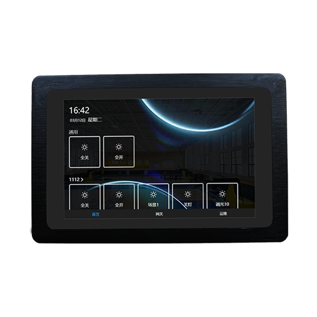
Plant operators already work with supervisory systems. A lighting upgrade should not automatically force them to manage another isolated interface for routine tasks. Where the project requires it, the lighting network can be integrated with the existing HMI or SCADA environment through the gateway and the required software interface.
The first step is to decide which lighting information actually matters. Operators may need zone status, fixture or loop alarms, communication status, schedules, manual commands, or selected maintenance information. They usually do not need every available data point on the main control-room screen.
Defining the data set first keeps the integration useful. It also reduces unnecessary alarm traffic. If the lighting system sends every minor event into the plant’s supervisory environment, operators may receive more information without gaining better control. The integration should support decisions, not simply prove that two systems can exchange data.
Use APIs and SDKs for project-specific functions
The gateway itself does not need a new hardware design for every project. The client information specifies that gateway customization generally focuses on opening API or SDK interfaces so customers and system integrators can connect project-specific functions rather than redesigning the core gateway.
That creates a more practical path for SCADA integration. An integrator can map lighting status, schedules, alarms, and control commands into the required software environment while keeping the underlying PLC communication hardware consistent.
This is where customized industrial lighting solutions add useful value. The customization sits in data mapping, software functions, control logic, permissions, schedules, and system interfaces when those elements need to match the plant. It does not have to mean changing every physical device in the project.
Bring Control Down to the Luminaire Without Confusing Communication with Dimming
Keep the PLC command path and the dimming interface separate
Plant engineers often need more than feeder-level switching. Maintenance teams may want to control selected fixtures. Operators may want different output levels for maintenance, standby, or full-operation scenes. Fault management may also benefit from addressable field devices.
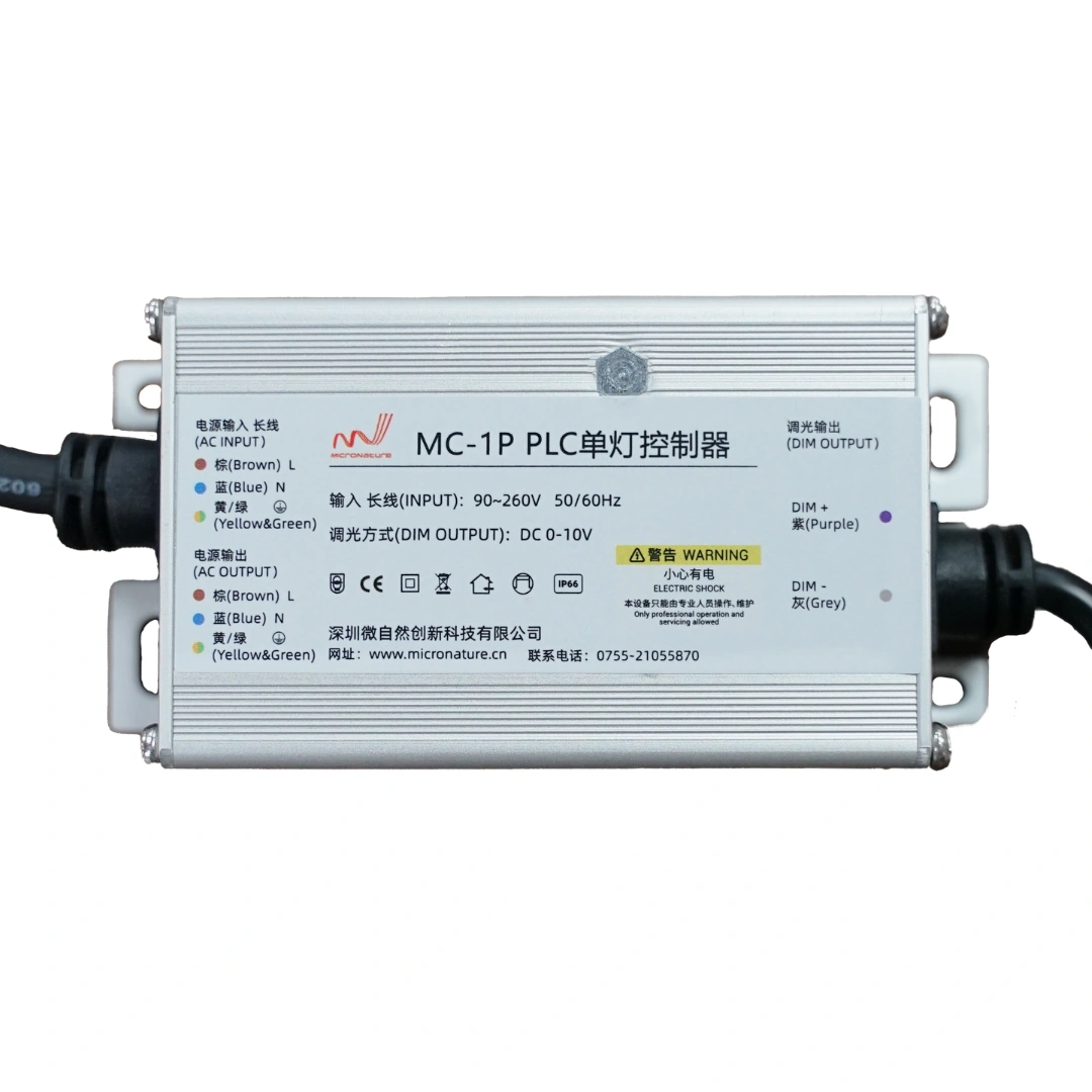
The PLC Light Dimmer Switch provides a field-level control point for these applications. One technical distinction matters during specification: PLC carries the communication command, while the dimming interface uses 0–10 V. PLC itself is not the dimming signal, and the product should not be specified as though it relies on DALI dimming.
This sounds like a small detail, but it affects driver selection and wiring. If the luminaire package comes from a separate supplier, the project team needs to confirm that the LED driver accepts the required dimming interface. Otherwise, the controls package and the luminaire package may each look correct on their own while failing to match at the final connection point.
The procurement specification should therefore describe both layers: how the field controller receives commands and how it sends the required dimming output to the driver. Keeping those functions separate makes coordination between the EPC contractor, control integrator, luminaire supplier, and commissioning team much easier.
Make Commissioning Part of the Design
Test the real feeder under representative plant conditions
A single-line diagram shows where circuits run, but it cannot predict every communication condition that will appear when the plant operates. Connected equipment, switching states, load changes, and local interference can alter the electrical environment.
For that reason, commissioning should do more than confirm that lights switch on and off. The team should test PLC communication across the intended segments, observe difficult locations, verify control response, and review whether the planned isolation boundaries still make sense under representative operating conditions.
If one section shows unstable behavior, the architecture gives engineers several ways to respond. They can shorten the communication domain, adjust an isolation boundary, review filtering, relocate sensitive field equipment, or investigate whether a connected device is introducing abnormal noise.
The same testing should include representative luminaires and drivers. Different power supplies and LED drivers can present different electrical characteristics on a circuit. Testing the final equipment combination gives a more useful result than validating every component independently and assuming the complete installation will behave the same way.
Design fault isolation and maintenance access before handover
Maintenance teams need to know where to look when something changes. Loop-level information, per-node alarms, segmented communication, and clear electrical boundaries can narrow a fault from “the lighting control system has a problem” to a specific feeder section or fixture group.
Local maintenance bypass at suitable isolator points can also help technicians work on a segment without turning troubleshooting into a plant-wide control issue. The project brief should define how maintenance personnel isolate a section, how local lighting behaves during that work, and how the communication network returns to normal afterward.
Firmware management belongs in the maintenance plan as well. Remote updates can reduce site work, but plants should schedule them during appropriate maintenance windows and define how technicians verify operation afterward. The technology matters, but disciplined operational procedures often determine whether a technically capable system remains dependable years after handover.
Turn Procurement Requirements into an Engineering Brief
Give the industrial lighting solutions supplier the information that affects topology
The most useful RFQ for an industrial lighting solutions supplier does not begin with a controller quantity. It begins with the electrical environment. Procurement teams should provide the single-line diagram, feeder lengths, panel locations, approximate fixture quantities, luminaire types, control-zone requirements, generator and transformer locations, emergency-circuit boundaries, and the supervisory system that needs to exchange data with the lighting network.
Those details allow the system architecture to follow the actual plant. A 500-meter outdoor feeder and a compact turbine-hall circuit should not automatically receive the same segmentation strategy. A zone beside high-power equipment may need a different enclosure or isolation arrangement from a service road. A critical circuit may require independent control while a normal production area can use scheduled dimming.
The mark of a high-quality industrial lighting solution is therefore not how many functions appear on a product sheet. It is whether the gateway location, communication boundaries, field controllers, protection measures, software integration, and maintenance strategy match the real electrical network.
This also changes how equipment quantities should be estimated. Instead of buying a fixed number of controllers first and forcing the plant into that structure later, map the zones and feeders first. Then determine where gateways, isolators, loop controllers, and field-level devices belong.
Customize the right parts of the system
Power plants often need project-specific functions, but customization should follow a clear reason. If the plant needs a unique SCADA data map, alarm hierarchy, schedule structure, permission model, or maintenance workflow, software customization can solve a genuine operating requirement.
If the gateway already performs the required communication role, redesigning its hardware may add little value. The client background specifically notes that gateway projects generally retain the standard hardware and use API or SDK access for customer integration. That approach keeps the communication platform more consistent while still giving system integrators room to meet project-specific software requirements.
The same principle applies throughout the system. Use specialized shielding where the environment requires it. Add isolation where the feeder needs it. Choose local autonomy where the circuit requires independent operation. Avoid making every component “special” simply because the project carries the word industrial.
Start with the Single-Line Diagram, Not the Product List
The next step for a power plant lighting project is not to select model numbers. Start by marking the lighting feeders on the plant single-line diagram. Add the control room, distribution panels, feeder lengths, generator and transformer locations, fixture groups, emergency circuits, and the areas that require individual or zone-level control.
Then divide the plant into communication zones. Identify where the central gateway can remain in a lower-interference environment. Mark the sections that pass close to strong electromagnetic sources. Decide where isolator boundaries can prevent one difficult electrical area from affecting another. Group local fixtures into practical loops and define which circuits need independent fallback.
After that architecture is clear, match the hardware to each layer. Use the Industrial PLC Gateway where the lighting network needs to connect with the supervisory layer. Use the PLC Loop Controller to organize local fixture groups. Use the PLC Light Dimmer Switch where addressable field control and 0–10 V dimming are required.
For an upcoming power plant lighting project, prepare the feeder topology, circuit lengths, fixture schedule, control zones, high-interference locations, emergency-lighting requirements, and SCADA interface needs before requesting the final configuration. MicroNature can then help evaluate the appropriate PLC gateway, loop controllers, field-level devices, and project-specific integration requirements for the actual plant.