
MN-L90S-R Single-Phase Power Line Communication Module for Smart Grid and Energy IoT Applications
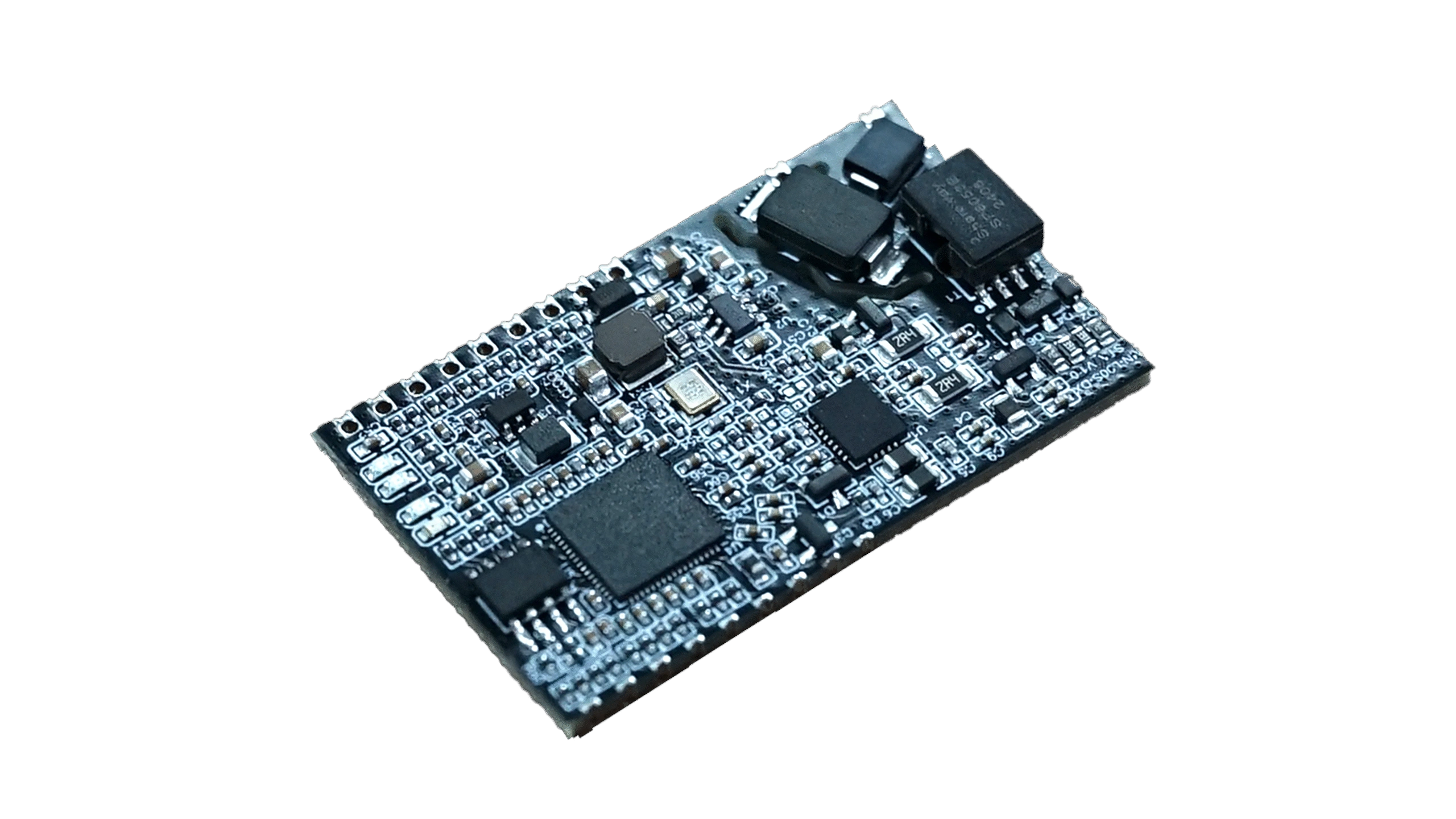
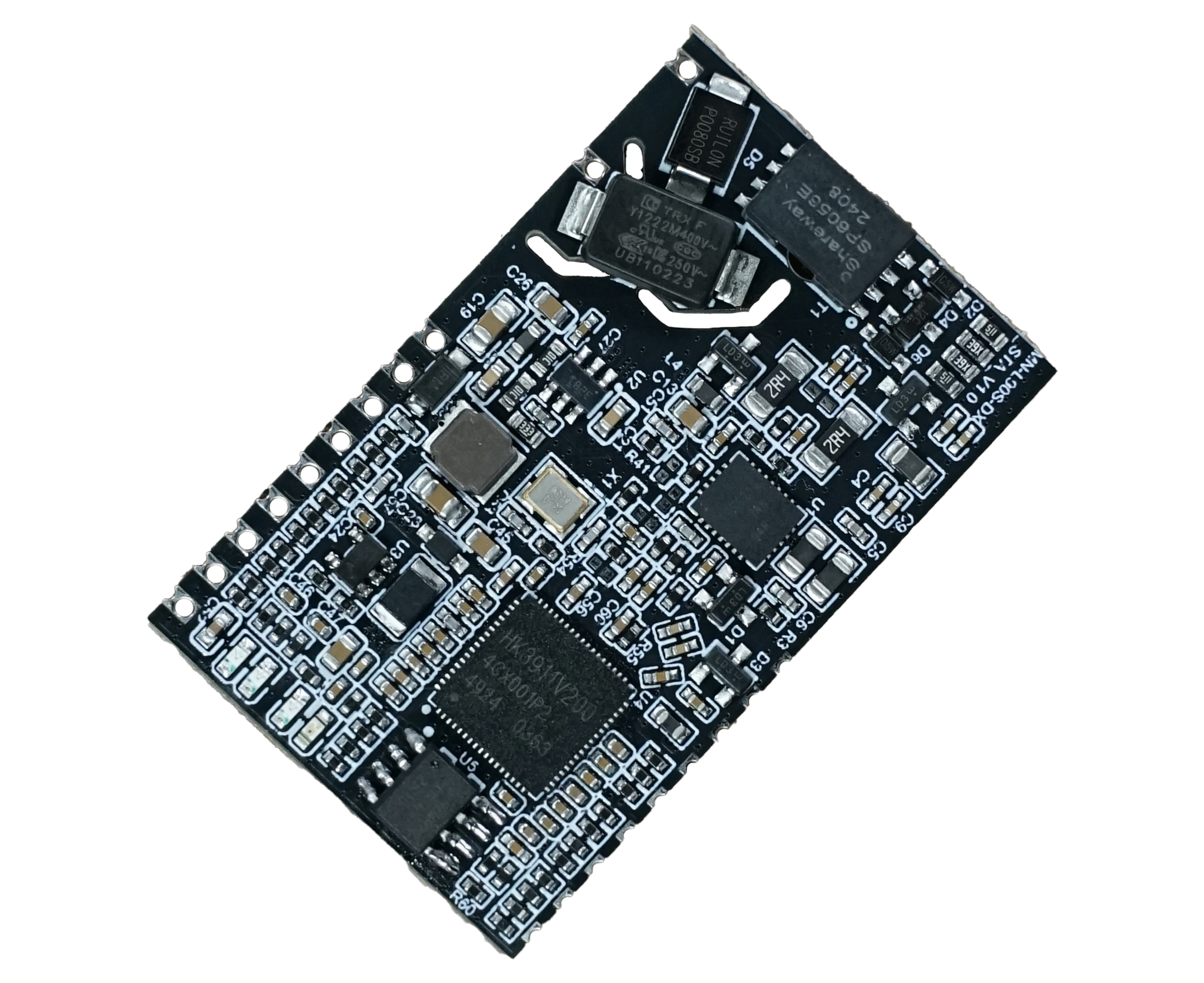
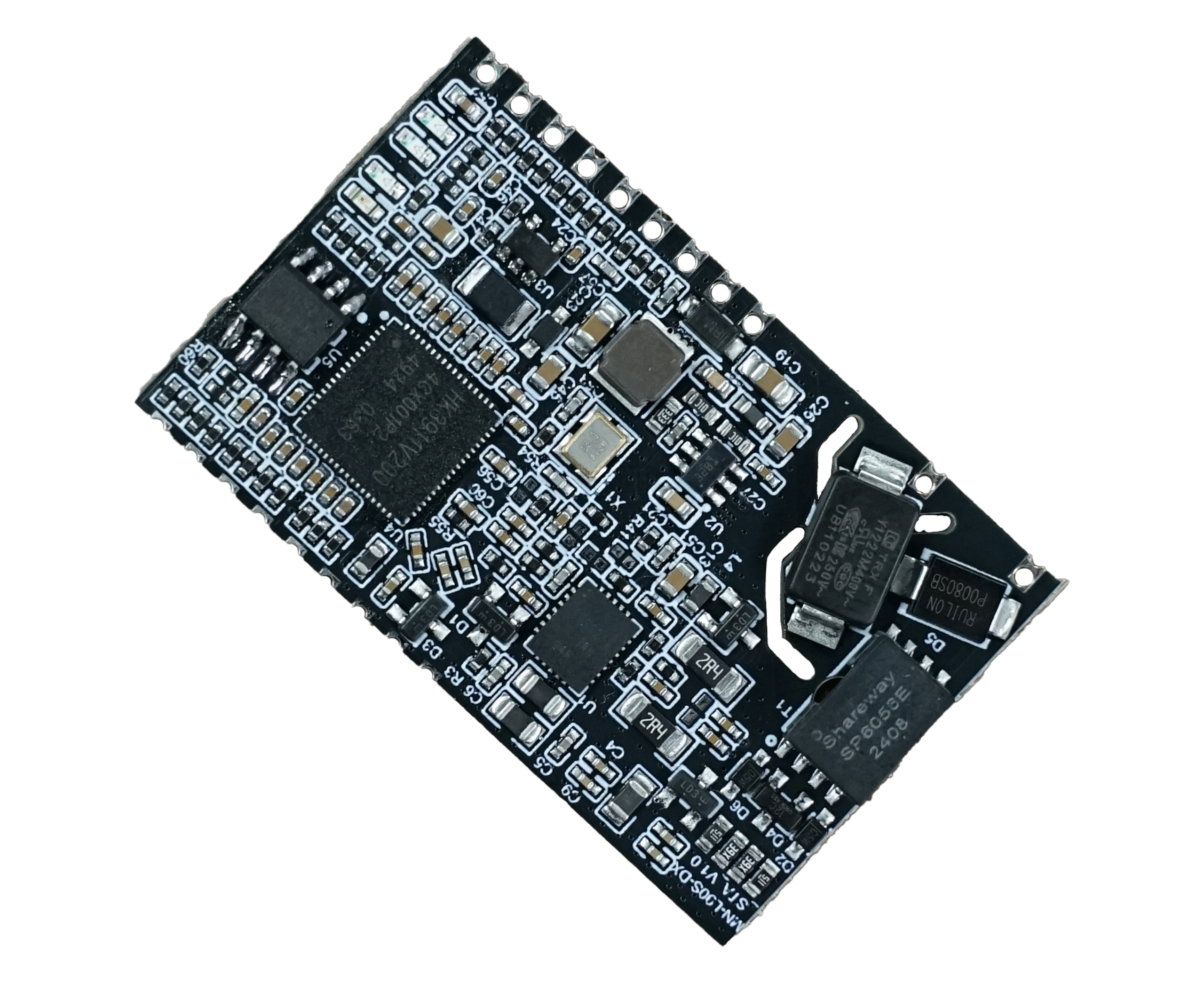
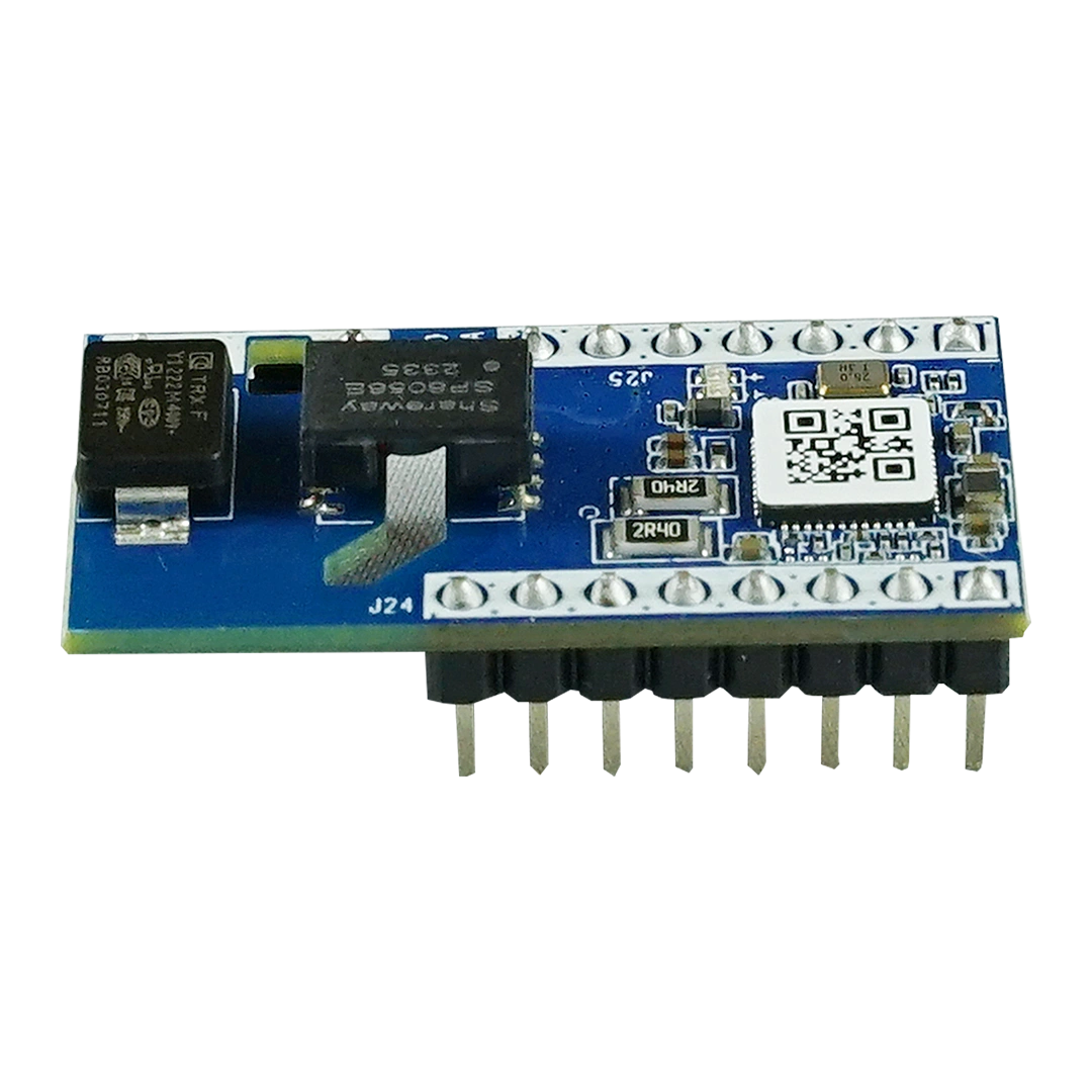
The MN-L90S Three-Phase Power Line Communication (PLC) Module is a broadband PLC communication module designed for reliable data transmission over existing three-phase power lines. Built for smart energy and industrial IoT applications, it enables stable communication without requiring additional communication cables.
Designed for smart meters, photovoltaic (PV) inverters, battery energy storage systems (BESS), EV charging stations, smart distribution networks, and energy management systems, the MN-L90S supports high-speed OFDM communication with excellent anti-interference capability.
By utilizing existing electrical infrastructure as the communication medium, the module significantly reduces deployment costs while improving installation efficiency and long-term reliability.
Reference Standards
- China Southern Power Grid Co.,Ltd.”Interface Protocol for Local Communication Module of Metering Automation Terminal”
- China Southern Power Grid Co.,Ltd.”Low-voltage power line broadband carrier communication protocol Part 1-6″Q/CSG1204111 -2022
- China Southern Power Grid Co.,Ltd.”Technical Manual for Advanced Applications of Low-Voltage Power Line Broadband Carrier”
- State Grid Corporation of China “Technical Specifications for Power User Electricity Consumption Information Collection Systems: Technical Specifications for Communication Units” Q/GDW1374.3-2013
- State Grid Corporation of China’s series of technical specifications for “Electricity User Power Consumption Information Collection Systems:Communication Unit Technical Specifications” – Q/GDW 374.3-2009
Product Advantage
Terminology
- CCO:Central Coordinator –the primary node in a power line carrier communication network.
- STA:Segment Termination Adapter –a word node in power line carrier communication networks.
- PCO:Proxy Coordinator –a relay node in power line carrier communication networks.
- OFDM:Orthogonal Frequency Division Multiplexing,an orthogonal frequency division multiplexing technology.
- BPSK:Binary Phase Shift Keying,binary phase shift keying.
- QPSK:Quadrature Phase Shift Keying,an orthogonal phase-shift encoding scheme.
- QAM:Quadrature Amplitude Modulation,also known as orthogonal amplitude modulation.
- FEC:Forward Error Correction,forward error correction encoding.
- CRC:Cyclical Redundancy Check.
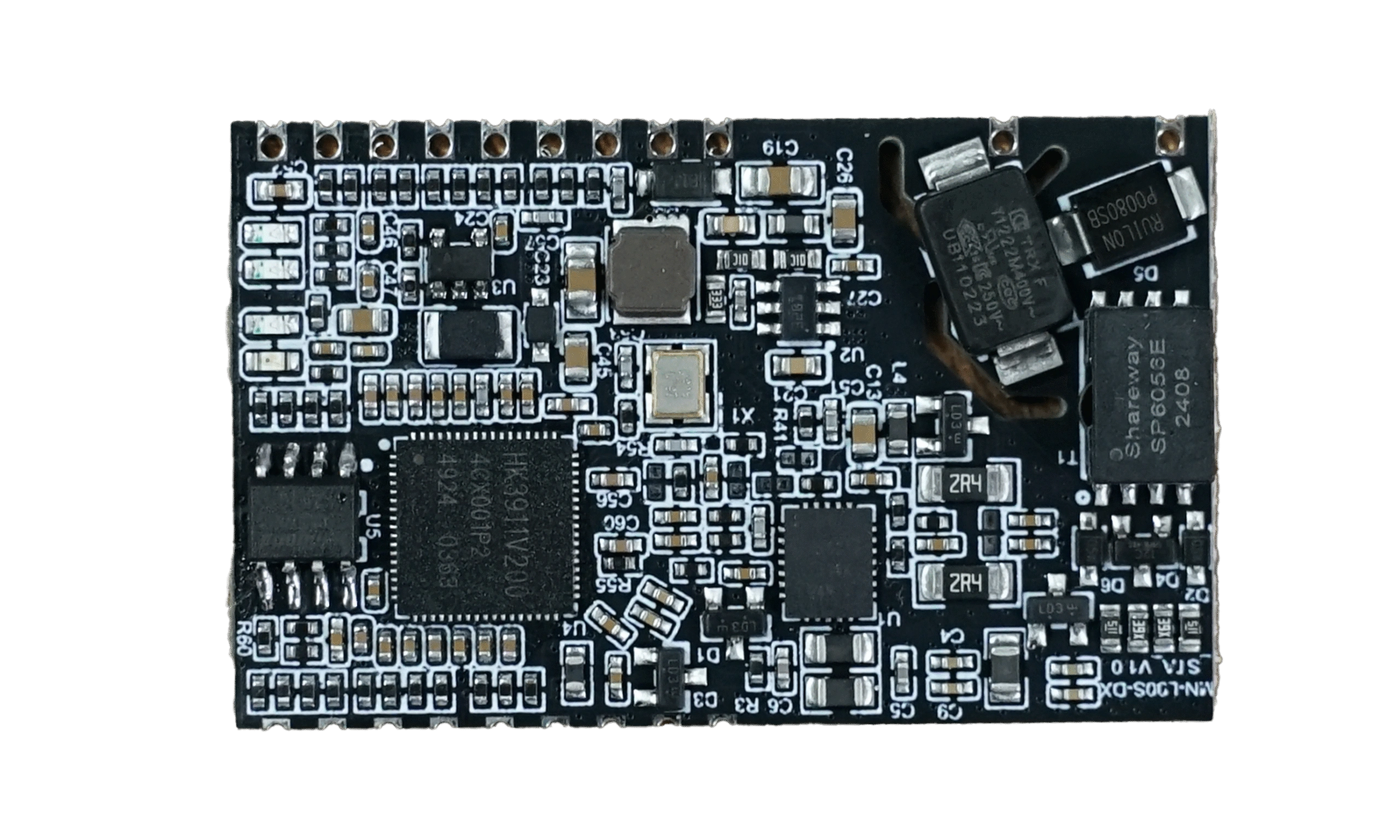
- Product Specifications
operating ambient
temperature
-25°C to +75°C Humidity (RH) ≤95% (non-condensing) Atmospheric Pressure 63.0KPa to 108.3KPa (Altitude below 5000m) Power Supply DC 12V±1V Power Consumption Standby <0.5W, Active <1W Voltage Range 0-220V Carrier Method HPLC Frequency Band 0.7MHz - 12MHz (configurable band segmentation) Modulation Method OFDM Serial Port Type
TTL/UART Flow Control
Baud Rate 9600bps (supports 2400-1039063bps) Data Bits 8 Stop Bits 1 check bit
No validation
Port Type TTL (HDR1X3) Baud Rate 115200bps Data Bits 8 Stop Bits 1 check bit
even parity check
Transmission Power
Adjustment
The transmission power can be adjusted using the AT command mode.
Logical topology
identification
The topology diagram primarily displays node information and hierarchical relationships within the current network,reflects overall communication quality, and identifies potential locations of communication failures.
asset management
Support the concentrator to query asset information such as MAC address,software/hardware version,and asset number
Remote Upgrade
Supports remote software version updates for modules
Insulation Resistance Power circuit to ground: >20MΩ Dielectric Strength Power circuit to ground: 4KV/ 1 min ESD Immunity Contact discharge: 6KV; Air discharge: 15KV Surge Immunity Test Power circuit: ±6KV Power LED (Red) Power indicator light:Should remain normally lit after power-on;flickering or extinction indicates malfunction
Status LED (Blue) Module status indicator:flashes when sending data
UP_TX lamp
(Blue)The light is on indicating that the local communication unit is transmitting data upstream.
UP_RX lamp
(Blue)The light is on indicating that the local communication unit is receiving data upstream
PCBA Size (L*W*H) 45mm × 28mm × 5mm
Why Choose MN-L90S-R
- Uses existing power lines for communication
- No additional communication wiring required
- Lower installation and maintenance costs
- High-speed broadband PLC networking
- Excellent resistance to electrical noise
- Stable communication over long distances
- Easy integration through RS485 interface
- Supports remote firmware updates
- Suitable for large-scale smart energy deployments
- Industrial-grade reliability for 24/7 operation
Module Dimensions and Mounting Hole Diagram
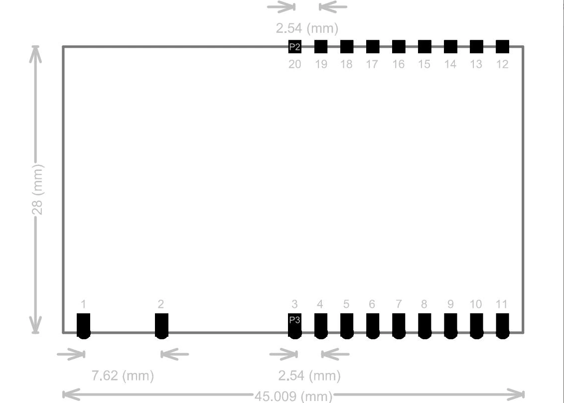
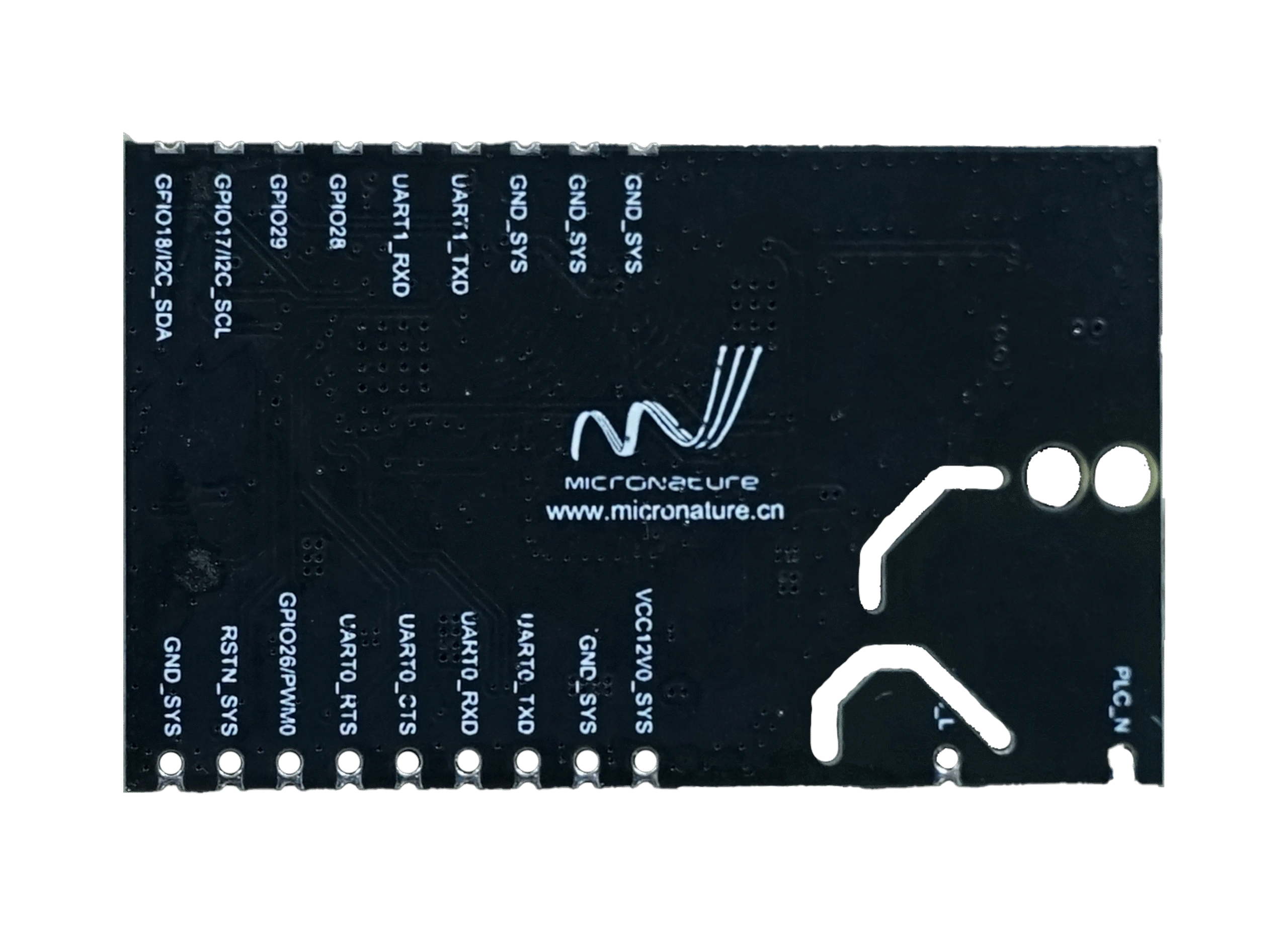
Pin Specifications
|
MN-L90C-R Power Line Communication Module PIN Definitions |
||
|
Pin Number |
Signal Definition |
explain |
| 1 |
PLC-L |
220V~N;Communication port requires a filtering network designed to isolate it from other AC power sources;generally required. Protection capability:Differential mode/Common mode:+/-4 kV |
| 2 |
PLC-N |
220V~L;Communication port requires a filtering network designed to isolate it from other AC power sources;generally required. Protection capability:Differential mode/Common mode:+/-4 kV |
| 3 |
VCC12V0 |
System power input:DC,12 V voltage;input power not less than 4 W |
| 4 |
GND |
Systematically |
| 5 |
UART0_TXD |
The module uses this UART for upper-level MCU communication by default. Reused Signal 0:UART0_TXD Mainboard Communication TX. Reused Signal 1 :GPIO_10 General I/O,supporting user-friendly IO operations Reused Signal 2:UART0_N_TXD UART TX Inverted Output |
| 6 |
UART0_RXD |
The module defaults to using this UART for upper-level MCU communication (with built-in 10K pull-up support). Reused Signal 0:UART0_RXD – Mainboard Communication UART Receiver Reused Signal 1 :GPIO_9 – Universal Input/Output,providing user-friendly I/O functionality |
| 7 |
UART0_RTS |
Default module flow control pin output (the module provides a 10 kV pull-up internally) Reuse Signal 0:Output from the flow control pin of RTS0_N UART0 Reused Signal 1 :GPIO_24 – Universal Input/Output,supporting user-defined IO functions |
| 8 |
UART0_CTS |
Default module flow control pin output (the module provides a 10 kV pull-up internally) Reuse Signal 0:Output from the flow control pin of RTS0_N UART0 Reused Signal 1 :GPIO_24 – Universal Input/Output,supporting user-defined IO functions |
References for Hardware Design
Power Input Requirements
| MIN | TYP | MAX | UNIT | |
| VCC12V0 | 11 | 12 | 13 | V |
Proximity to the module's 12 V input on the motherboard requires at least one pair of 22 μF +0.1 μF ground energy storage and decoupling capacitors to reduce power ripple,with peak-to-peak ripple below 200 mVpp.
The 12V module shares a 600 Ω/100 MHz ferrite bead isolation circuit with other 12V components on the motherboard,with a current rating of 1 A or higher.
The module's input power supply must meet a minimum requirement of4 W.
Typical Applications
The MN-L90S-R is widely used in:
- Smart Metering Infrastructure (AMI)
- Smart Grid Communication
- Energy Management Systems (EMS)
- Battery Energy Storage Systems (BESS)
- Three-phase PV Inverters
- Hybrid Solar Inverters
- EV Charging Stations
- Industrial Energy Monitoring
- Smart Buildings
- Factory Energy Management
- Distribution Automation
- Utility Monitoring Networks
FAQ
What is the MN-L90S-R PLC Module used for?
The MN-L90S-R is a broadband power line communication module designed for smart energy applications including smart meters, PV inverters, energy management systems, EV chargers, and industrial IoT devices.
