
MN-80X-DIP PLC Communication Module for Smart Lighting and IoT Applications
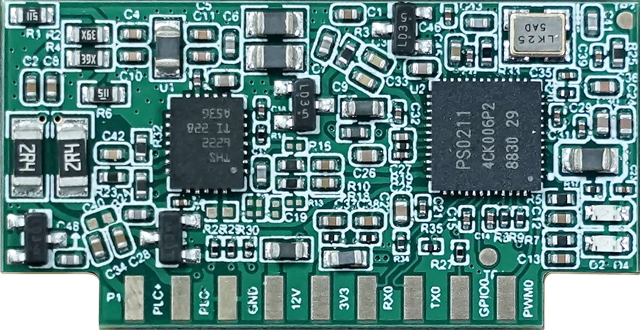
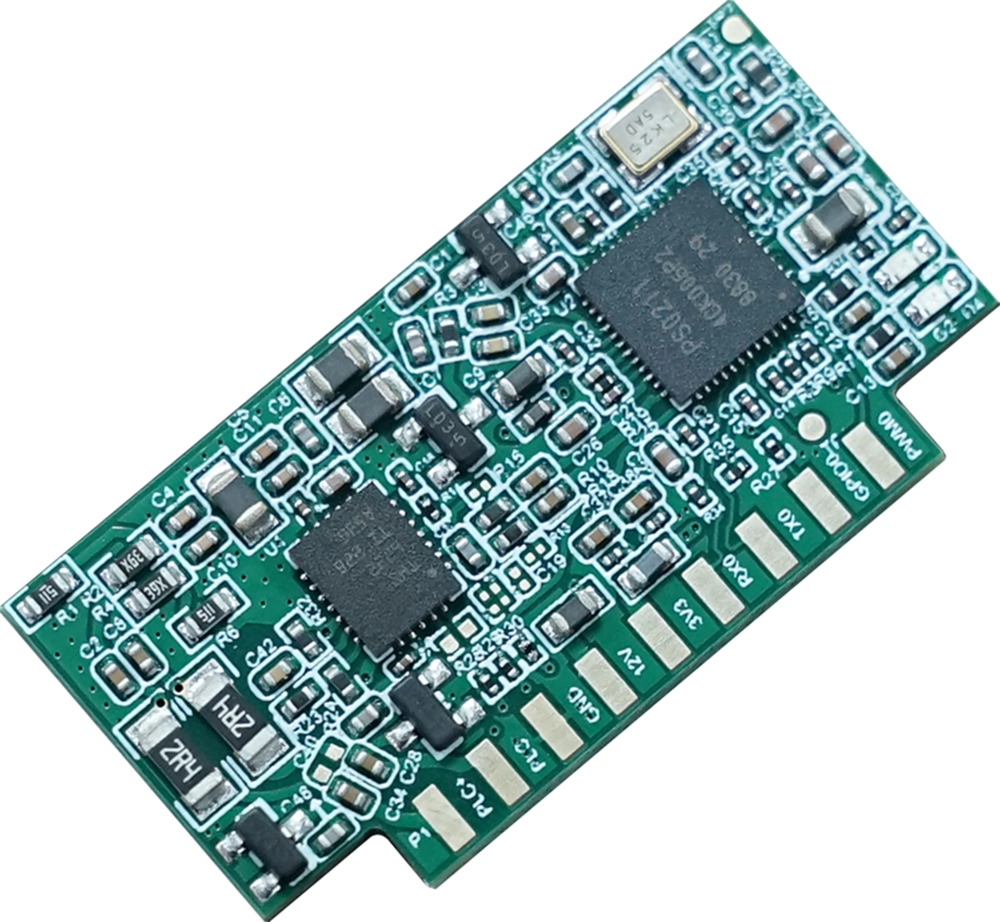
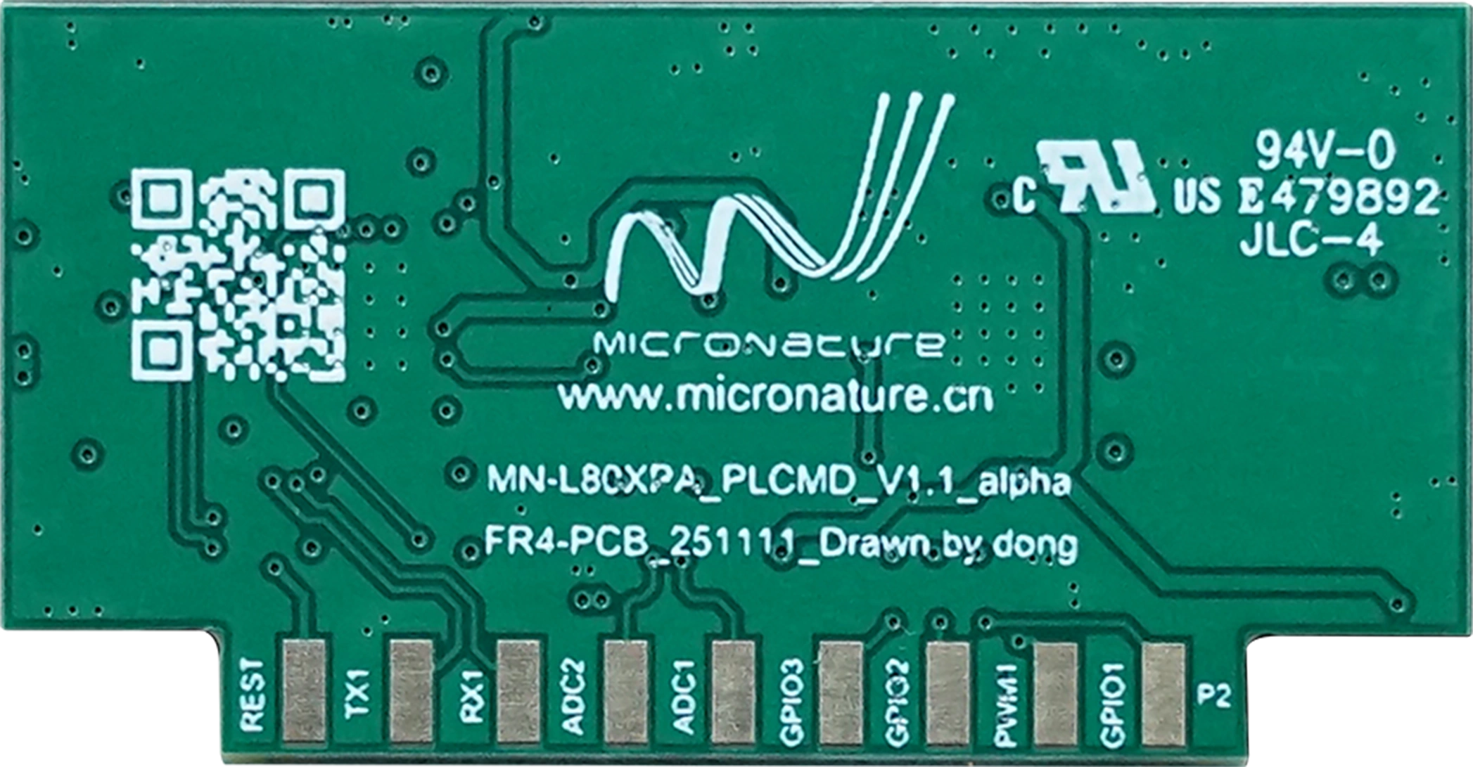
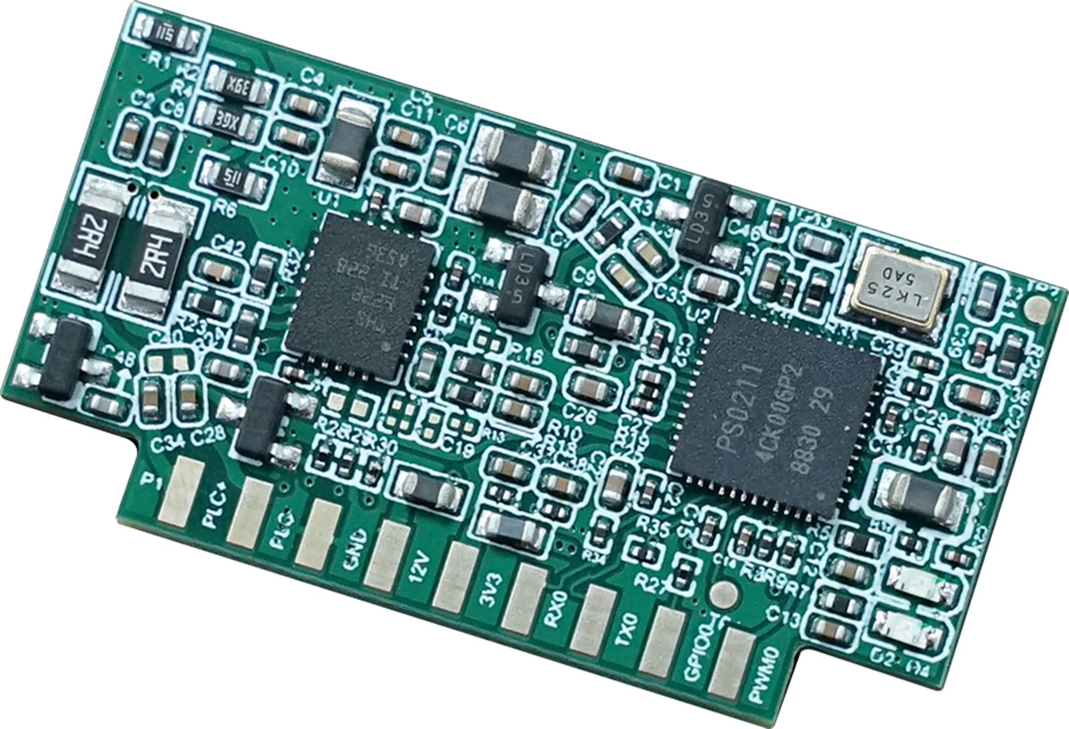
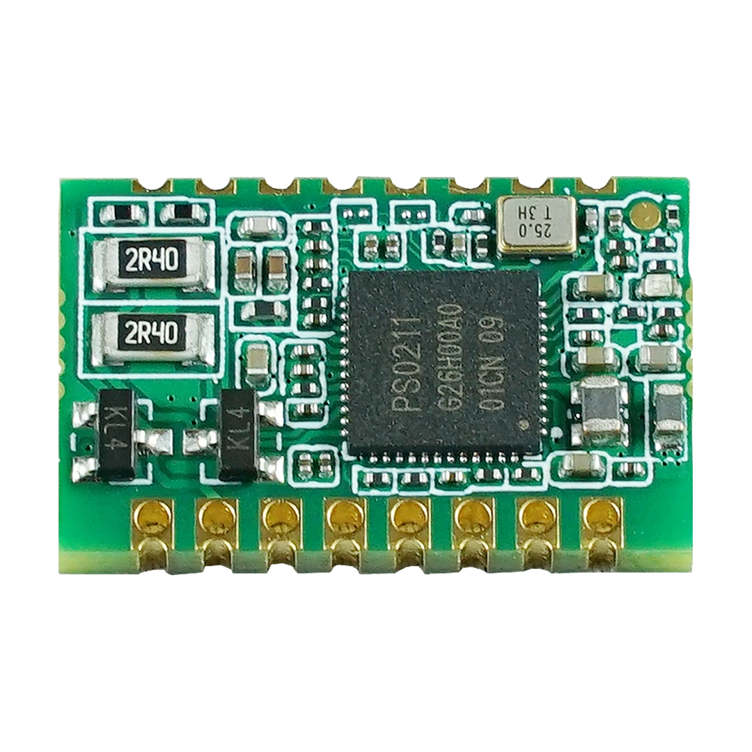
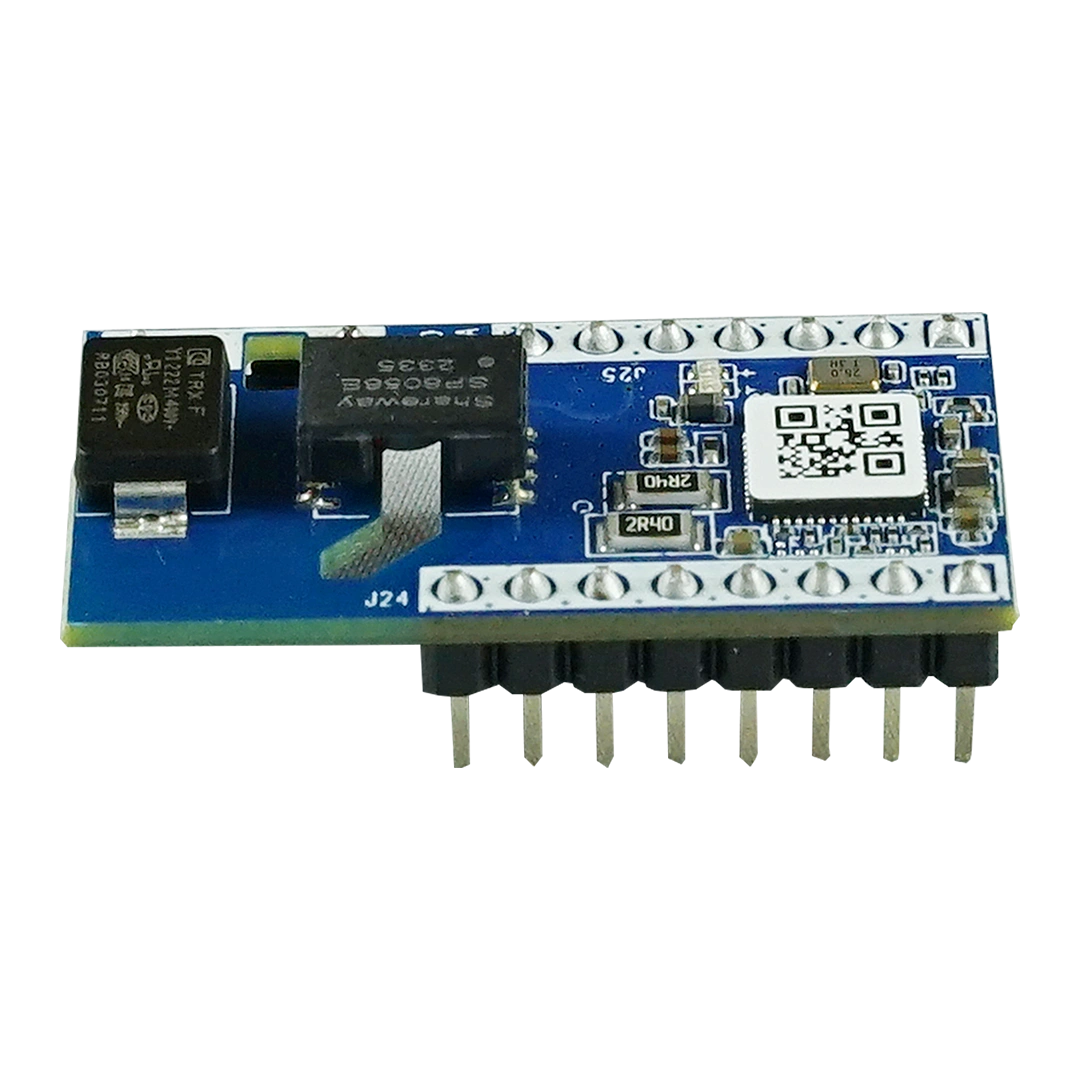
The MN-80X-DIP Power Line Communication (PLC) Module is a high-performance embedded PLC communication solution designed for smart lighting, smart city infrastructure, industrial IoT and energy management applications.
Using existing power lines as the communication network, the module enables reliable data transmission without requiring additional communication wiring. It integrates an ARM Cortex-M3 processor, IEEE P1901.1-compatible PLC modem, OFDM/FSK modulation technology and multiple peripheral interfaces including UART, PWM and GPIO.
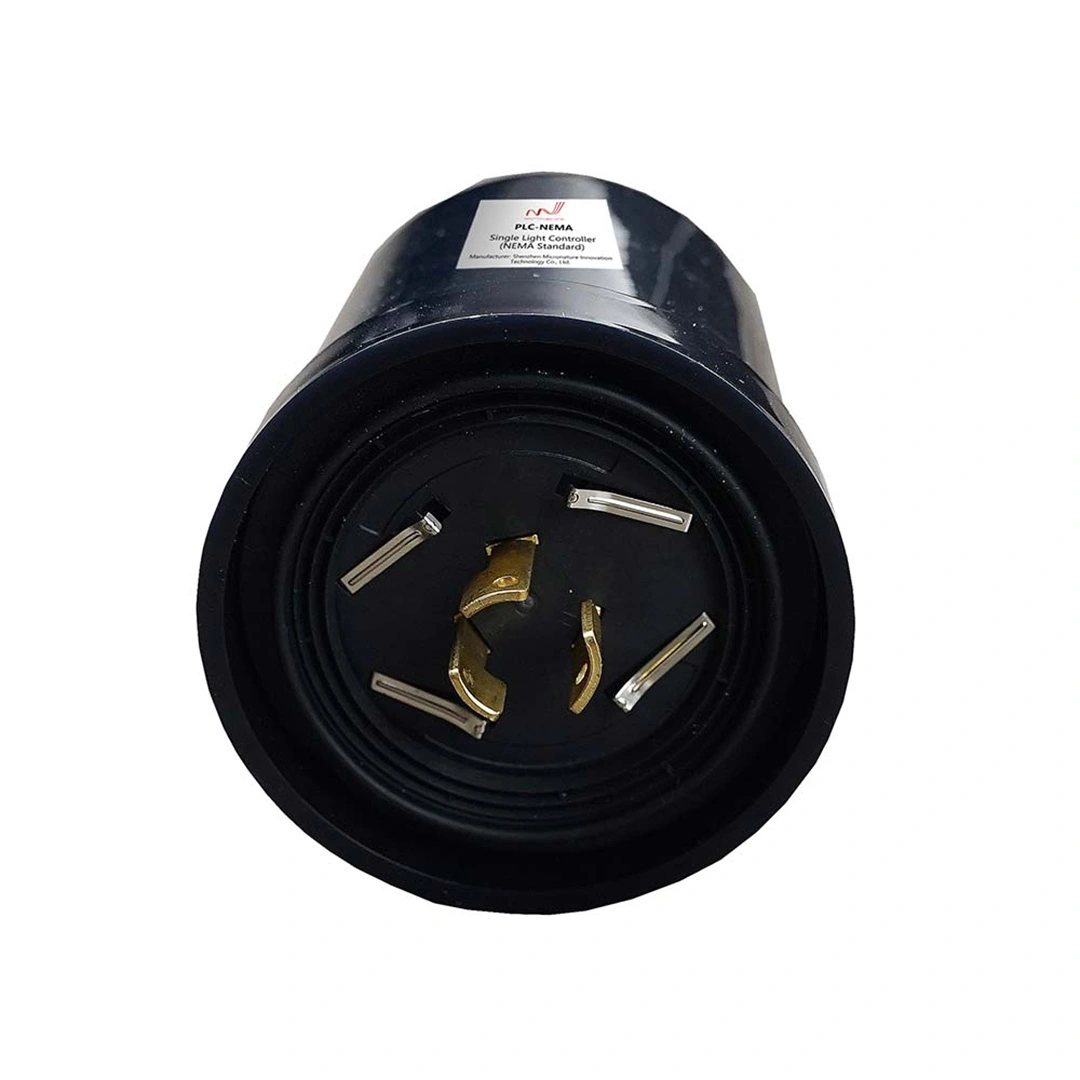
With its compact P2.54mm DIP design and enhanced external PA transmission solution, the MN-80X-DIP provides stable long-distance communication performance for PLC-based smart devices, including LED controllers, smart street lights, IoT terminals and industrial automation equipment.
What is the MN-80X-DIP PLC Module?
The MN-80X-DIP is an embedded Power Line Communication (PLC) module that enables data communication through existing electrical power lines. It is designed for smart lighting, smart city, industrial IoT and energy management systems requiring reliable wired communication without installing new communication cables.
Product Advantage
1) CPU and Memory Performance
- High-performance Cortex-M3 processor with a clock speed of 200MHz
- Embedded SRAM 256KB
2) Communication Index
- Compatible with the IEEE1901.1 (PLC-IoT) standard subset, chips utilizing this subset enable seamless interoperability.
- Communication frequency band: 0.076MHz-5.7MHz, with five adjustable segments: 2.5MHz-5.7MHz (high-speed), 0.5
MHz-3.7MHz, 0.7MHz-3MHz, 0.2MHz-0.47MHz, and 0.076MHz-0.145MHz (low-speed anti-interference). Subcarriers
are configurable. - The peak rate of the physical layer is 0.507 Mbit/s, and the application layer rate is 80 Kbps.
- The receiving sensitivity is superior to 0.2 mVpp (approximately-110 dB, laboratory conditions), with stable reception under
strong noise. - Featuring OFDM technology, it supports BPSK/QPSK modulation modes with FEC and CRC functions, offering robust noise
reduction and error correction capabilities.
3) MAC Characteristic
- The hybrid access method combines TDMA (Time Division Multiple Access) with CSMA/CA (Carrier Sense Multiple Access with Collision
Avoidance). - Supports time slot allocation, allowing dedicated time slots for different nodes based on service requirements to improve real-time performance and
reliability. - Supports data segmentation and reassembly, enabling fragmented transmission of data exceeding the maximum frame length of the MAC layer.
- Provides retransmission and CRC check to ensure data transmission accuracy
- Supports multi-level QoS (typically 4 levels), allowing different priorities for control commands, meter reading data, status reports, and other services.
4) Networking Characteristics
- The tree network consists of three types of nodes: CCO (core node, responsible for network construction and management), STA (terminal),
and PSTA (relay). - A single CCO can handle up to 1,000 nodes, with a typical 500-node, 2-tier scenario completing auto-networking in 10 seconds.
- Supports 15-level relay, dynamic routing, and multi-path addressing, automatically switching to the optimal path during network fluctuations
- Supports unicast, multicast, and broadcast; hardware AES128/256 with whitelisting and secure boot capabilities
5) Module Power Consumption
- Static power consumption (listening) <100mW@3.3V
- Power consumption in idle state <50mW@3.3V
- Dynamic power consumption (full-power emission) <700mW@3.3V
- Dynamic power consumption: Typical 12V (full configuration mode) <4.074W @50 ohm load + 16Vpp,
typical value <1300mW@50 ohm load + 16Vpp - Maximum power consumption: 3.3V, maximum current: 220mA; typical 12V, maximum current: 330mA
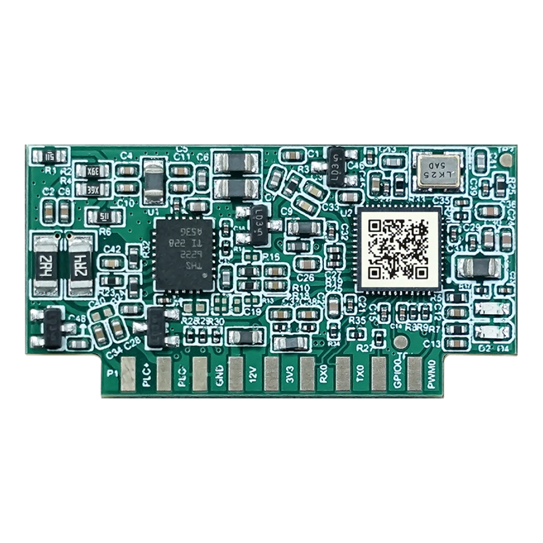
- Technical Parameters
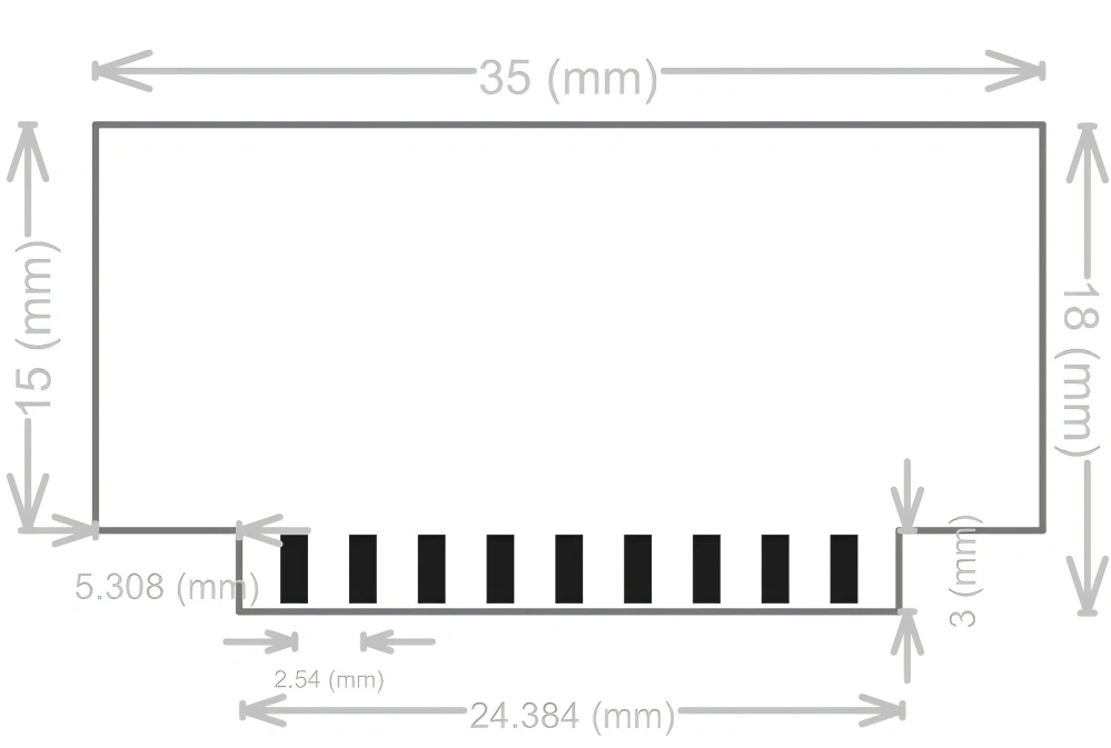
- Module Packaging and Pin Definition
- Operating voltage range: 3.3V ±10%,8V-32V (typically 12V ±10%)
- Operating temperature range: -40℃ to 85℃
- Storage temperature range: -40℃ to 125℃
35mm*15mm(18mm)*1.6mm
PLC smart lighting network architecture using MN-80X-DIP communication module 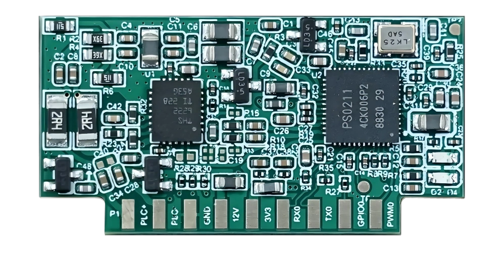
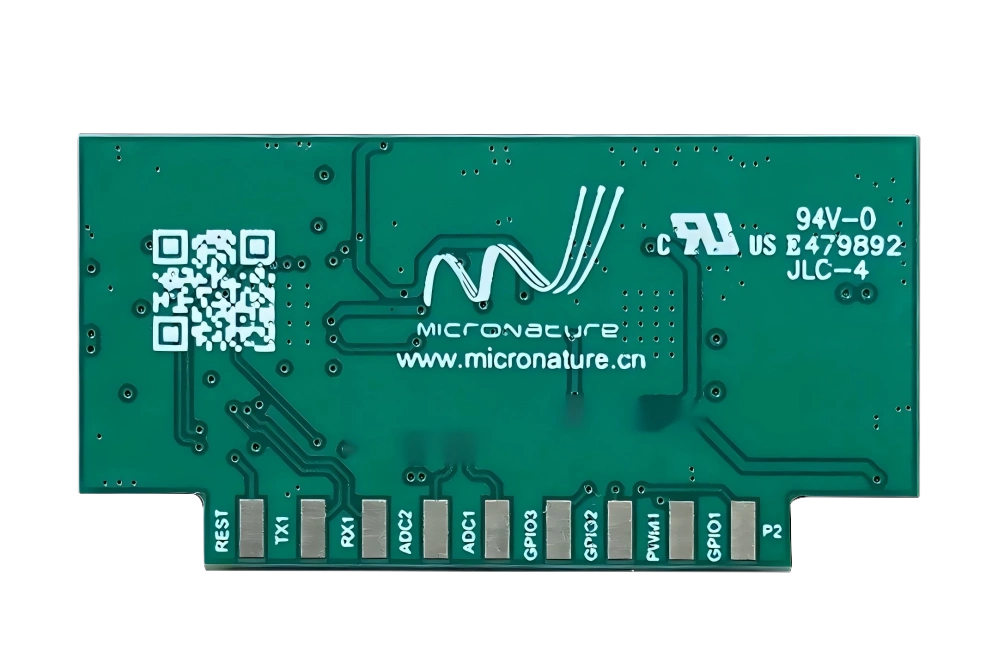
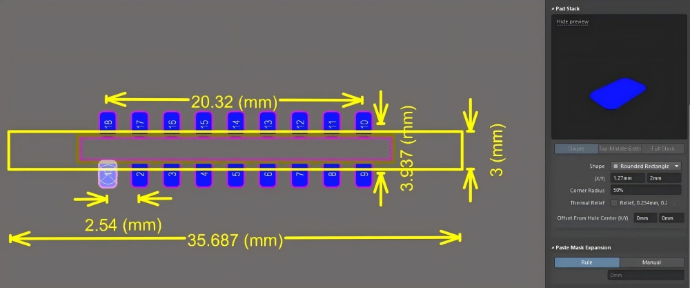
Pin definition and multiplexing instructions:
PIN order number PIN definition Multiplexing signals and other instructions Front-side pin distribution of the gold finger (pins 1-9) 1 PLC+ PLC+ communication
The interface requires designing a filtering network to isolate it from other AC power sources; generally, protection capability is
required.
Power: Differential Mode/Common Mode: +/-4KV2 PLC- PLC-Communication port: A filtering network must be designed to isolate it from other AC power sources; generally
Protection level: Common-mode/ differential-mode: +/-4KV3 GND Scientific GND 4 12V PA power input 5 3.3V Power input 6 UART0_RXD GPIO9, Multiplexed Signal 1: UART0_RX (the default service port for external
MCU communication, with a 10K pull-down implemented in the module's internal
design)7 UART0_TXD GPIO 10, Multiplexed Signal 1: UART0_TX (the default service port for
external MCU communication, with a built-in 10K pull-up on the module)8 GPIO0 GPIO 15, General I/O Input/Output 9 PWM0 GPIO0, default multiplex signal 2: PWM_OUT 1 Distribution of the reverse pins of the gold finger (pins 9-18) 10 GPIO1 GPIO 16, General I/O Input/Output 11 PWM1 GPIO 19, Multiplex Signal 2: PWM_OUT 2 12 GPIO2 GPIO 17, General I/O Input/Output 13 GPIO3 GPIO 18, General I/O Input/Output 14 ADC1 VIN4, ADC input (module design with a series 75R currentlimiting resistor and a ground decoupling capacitor) 15 ADC2 VIN 5, ADC input (module design with a series 75R currentlimiting resistor and a ground decoupling capacitor) 16 UART1_RXD UART1_RXD, Multiplex Signal 0: This is the default input for UART1 data
reception, featuring a built-in 10kΩ pull-up resistor. It is used for programming
tests.17 UART1_TXD UART1_TXD, Multiplex Signal 0: This is the default input for UART1 TXD. The module'
s internal design includes a 10kΩ pull-up resistor, and UART1 data reception is used for
programming tests. 18 RST RSTN, System Reset Signal Input, Low Level Active18 RST RSTN, System Reset Signal Input, Low Level Active
User-Side Hardware Design Reference
1) Power Supply Input Design Requirements
- Place at least one 10uF/12V input capacitor (0.1uF to ground) and decoupling capacitor near the 3.3V/12V input terminals of the motherboard module to reduce power supply ripple, with peak-to-peak ripple below 100mVpp.
- Place a TVS diode near the 3.3V/12V input terminals of the motherboard module to dissipate surge currents.
- The 3.3V module and other 3.3V components on the motherboard use 600R/100MHz magnetic bead isolation with a current rating of 1A or higher.
- The 3.3V module circuit must provide a minimum current of 250mA or higher.
- The 12V circuit module must provide a minimum current of 350mA or higher.
2) User Side Signal Coupling Reference Circuit
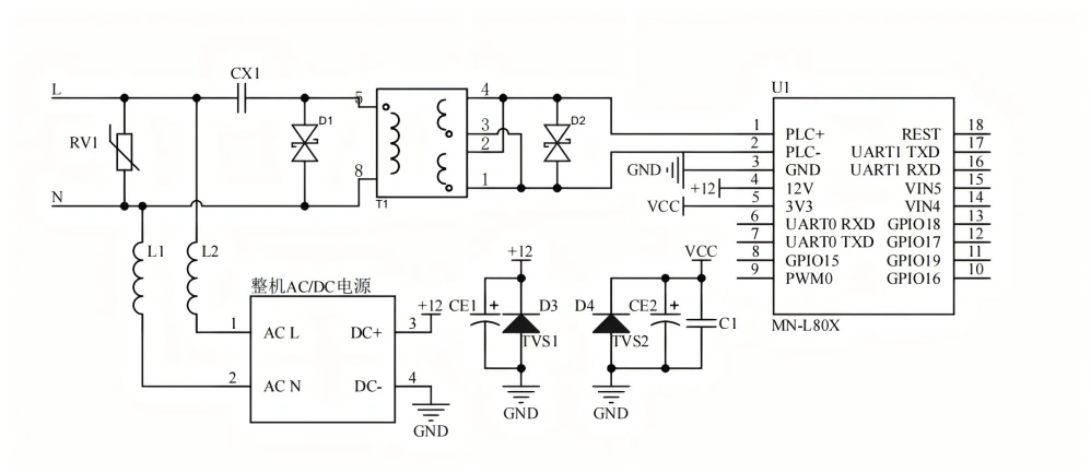
A Typical Single-phase AC Coupled Reference Circuit Diagram
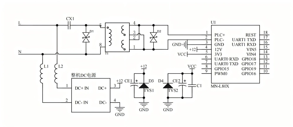
A Typical Single-phase DC Coupled Reference Circuit Diagram
3) CCO and STA Typical Networking
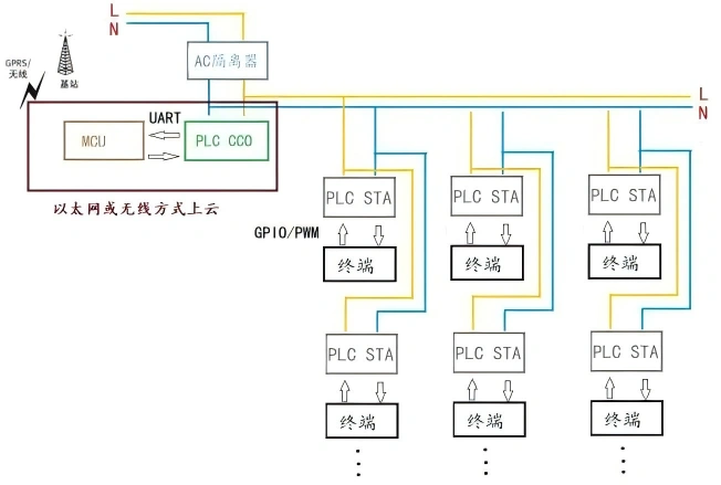
- CCO stands for PLC Central Controller, and STA stands for PLC Station.
- The CCO is hardware-compatible with the STA, but the software differs.
- In simple applications, CCO can operate independently without requiring an external MCU. For cloud-based networking, an external MCU is needed to establish the connection via wired Ethernet or wireless means.
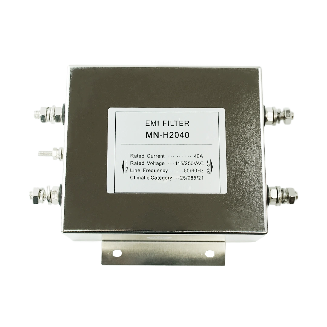
- In a typical CCO networking environment, it is recommended to install an AC220 isolator on the 220VAC line at the CCO front end to filter out noise from other power networks. This prevents interference with local CCO network communication quality and reduces the impact of local CCO on other PLC communication networks
Key Features of MN-80X-DIP PLC Module
1. IEEE P1901.1 Compatible PLC Communication
- Supports IEEE P1901.1 PLC-IoT standard subset
- OFDM and FSK modulation
- Stable communication in noisy power environments
- Physical layer data rate up to 0.507 Mbps
2. High-Performance Embedded Processor
- ARM Cortex-M3 processor
- 200MHz clock frequency
- 256KB SRAM
- Suitable for intelligent IoT terminal development
3. Enhanced Signal Transmission
- External PA solution
- Approximately 15dB transmission improvement compared with built-in PA design
- Reliable communication for large-scale PLC networks
4. Flexible Hardware Integration
Supports:
- UART
- PWM
- GPIO
- ADC interfaces
Suitable for:
- LED drivers
- Smart controllers
- Sensors
- Industrial IoT devices
| Feature | MN-80X-DIP PLC Module |
|---|---|
| Communication Technology | Power Line Communication |
| Standard | IEEE P1901.1 |
| Modulation | OFDM / FSK |
| Processor | ARM Cortex-M3 |
| Interfaces | UART, PWM, GPIO |
| Network Type | CCO / STA / Relay |
| Transmission Enhancement | External PA |
| Operating Temperature | -40℃ to +85℃ |
| Applications | Smart Lighting, IoT, Smart City |
Applications of MN-80X-DIP PLC Communication Module
Smart Street Lighting
The MN-80X-DIP enables communication between street lights, controllers and cloud platforms through existing power infrastructure, supporting remote monitoring, dimming control and energy management.
Smart Building Systems
Used for:
- Smart lighting control
- HVAC communication
- Building automation systems
Industrial IoT
Suitable for:
- Industrial sensors
- Automation equipment
- Energy monitoring devices
Smart Energy Systems
Applications include:
- Smart meters
- PV systems
- Energy management terminals
FAQ
What is the MN-80X-DIP Power Line Communication Module?
The MN-80X-DIP is an embedded PLC communication module that uses existing power lines for data transmission in smart lighting and IoT systems.
