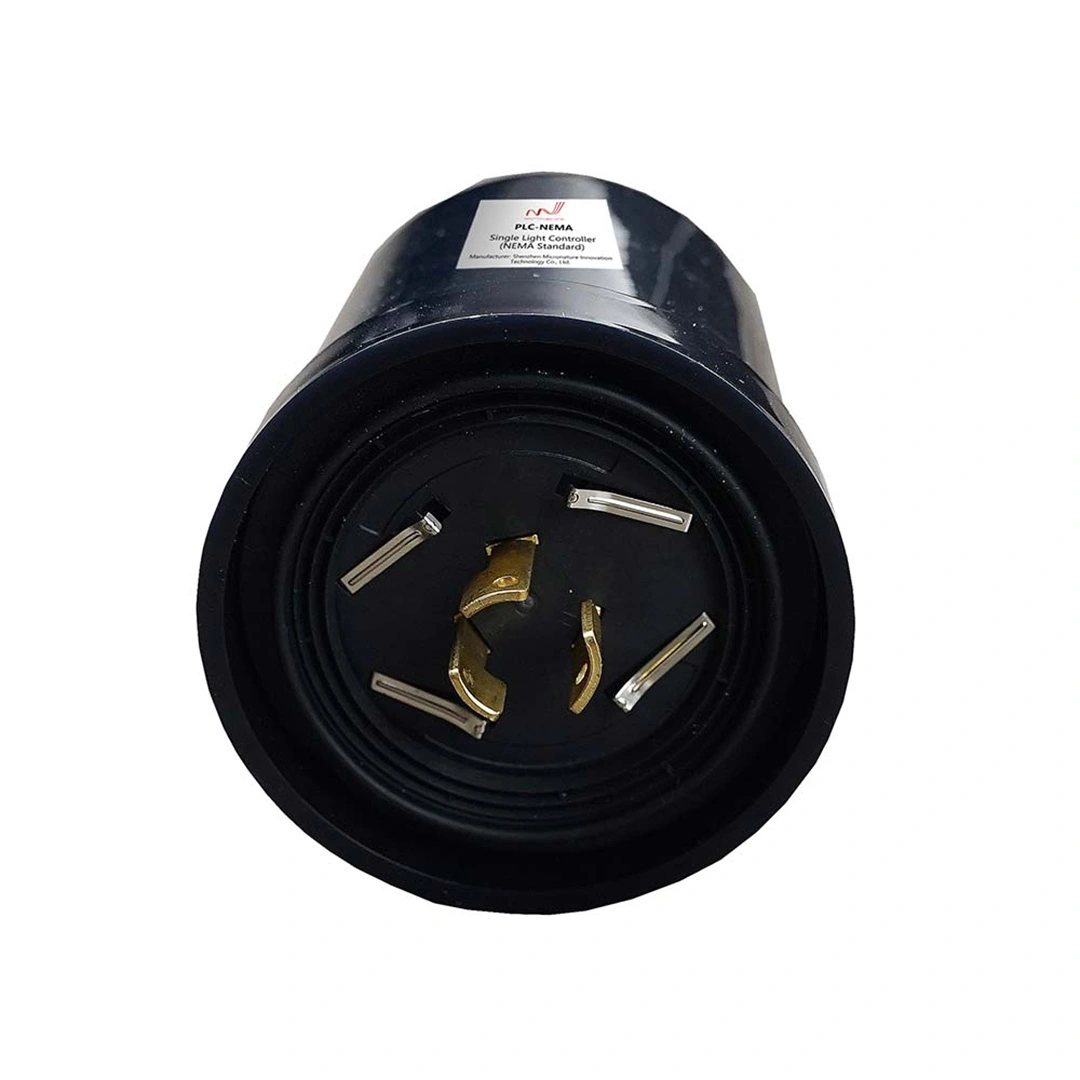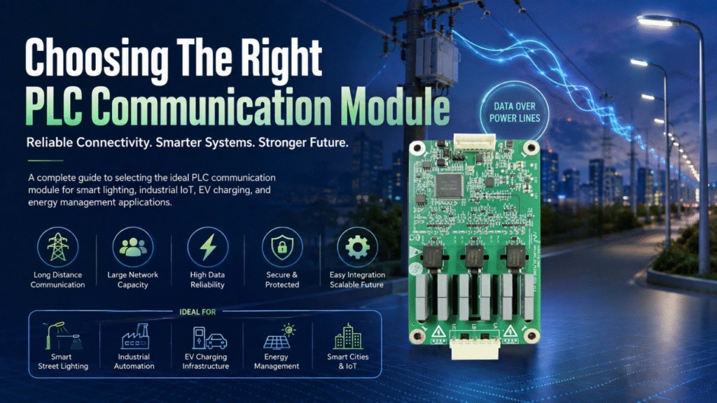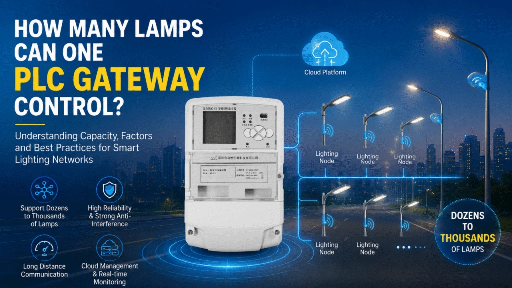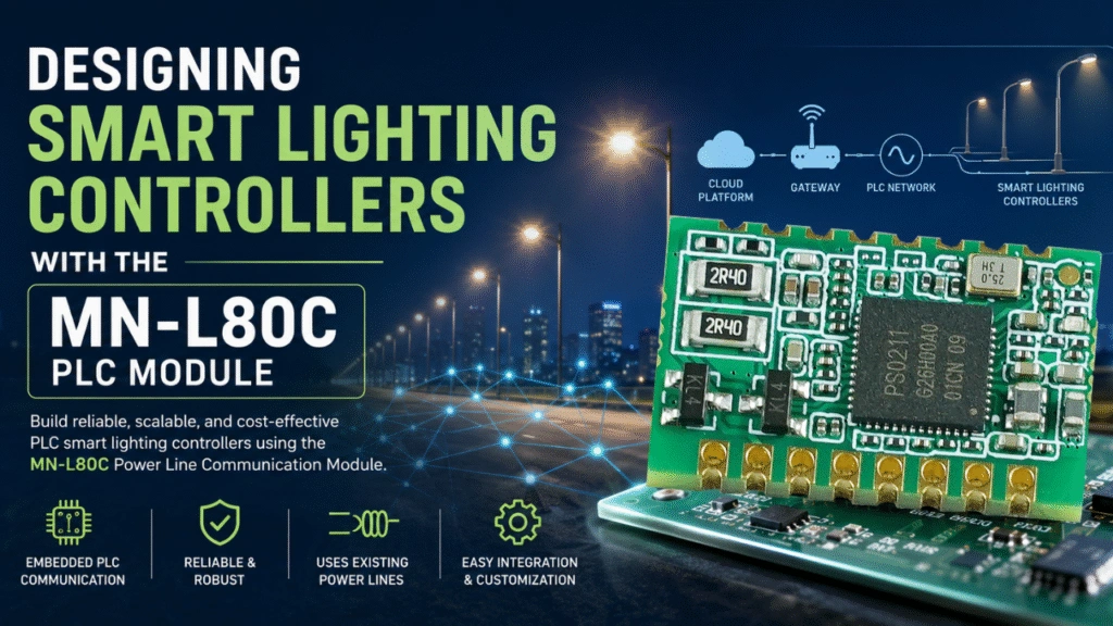
Designing a smart lighting controller requires more than adding remote on/off control to a conventional lighting system. Modern lighting controllers need reliable communication, flexible hardware interfaces, low installation cost, and the ability to operate over existing electrical infrastructure. The MN-L80C provides an embedded Power Line Communication (PLC) solution for manufacturers and system developers building smart lighting controllers.
The MN-L80C PLC Module provides an embedded Power Line Communication (PLC) solution for manufacturers and system developers building smart lighting controllers. Instead of installing a separate communication cable, a PLC-based controller can transmit control and data signals through the existing power lines.
This article explains how to design a smart lighting controller around the MN-L80C PLC Module, including the controller architecture, hardware interfaces, PLC communication, firmware considerations, network design, and practical applications.
What Is a Smart Lighting Controller?
A smart lighting controller is an embedded device that manages lighting equipment while providing communication and control capabilities.
Depending on the application, a smart lighting controller can support:
- Remote light on/off control
- Dimming
- Scheduling
- Energy monitoring
- Fault detection
- Device status reporting
- Group control
- Automatic networking
- Remote configuration
- Cloud or gateway communication
In a PLC-based smart lighting system, the controller communicates through the same electrical power network used to supply the lighting equipment.
This makes PLC technology particularly useful for street lighting, industrial lighting, warehouse lighting, tunnel lighting, parking areas, and other applications where installing additional communication cables can be expensive or impractical.
Why Use a PLC Module for Smart Lighting Controllers?
The MN-L80C can provide an embedded PLC module for OEM smart lighting controller designs. A smart lighting controller needs a reliable communication interface between the lighting device and the control system. Wireless communication can be useful in some environments, but radio signals may be affected by building structures, electromagnetic interference, distance, or installation conditions.
PLC provides another approach: using the existing power line as the communication medium.
A PLC-based lighting controller can combine:
Lighting power + PLC communication + control interfaces + embedded firmware
into a single controller architecture.
For OEM developers, an embedded PLC module such as the MN-L80C can simplify the communication portion of the design. The manufacturer can integrate the module with a custom controller PCB and develop application-specific firmware around it.
MN-L80C PLC Module Overview
The MN-L80C Power Line Communication Module is a compact PLC module designed for embedded applications.
Key characteristics include:
- Compact 20 × 11 × 2.4 mm form factor
- PS0211 PLC chipset
- ARM Cortex-M3 processor
- Support for IEEE P1901.1-related PLC communication
- OFDM/FSK communication technology
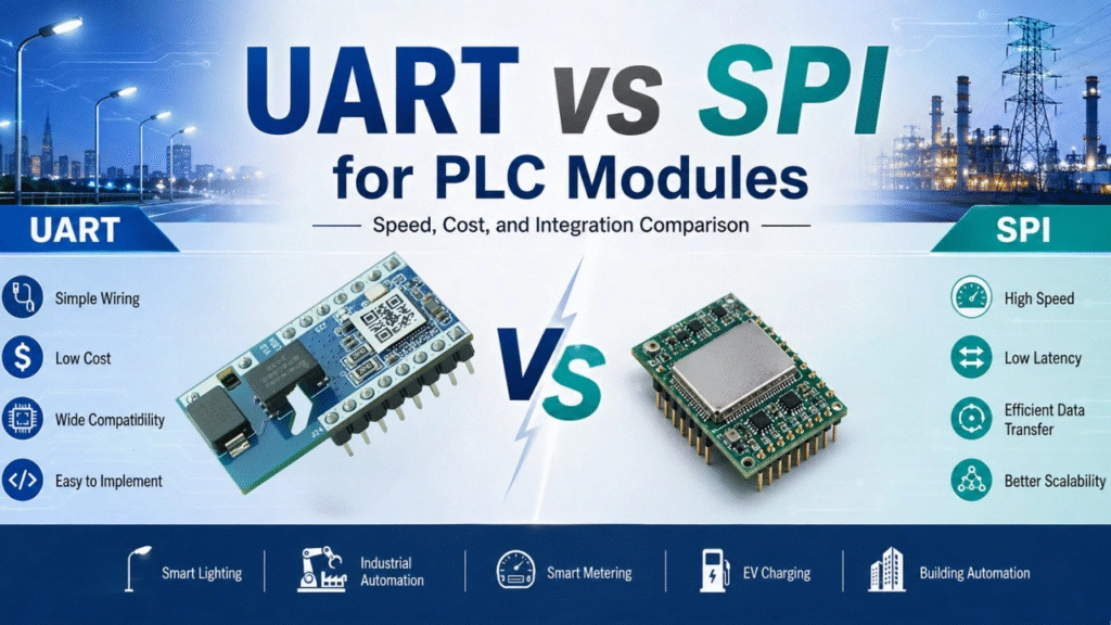
- UART interface
- PWM interface
- GPIO
- ADC
- Designed for embedded integration
The module provides the PLC communication foundation while allowing the lighting controller manufacturer to implement the application-specific functions required by the final product.
This architecture is useful for OEM and ODM developers because the PLC communication function does not need to be designed entirely from the beginning.
Basic Architecture of a Smart Lighting Controller
A smart lighting controller built around the MN-L80C can be divided into several functional blocks.
1. AC Power Input
The controller receives power from the existing electrical line.
The power section typically includes:
- AC input protection
- EMI filtering
- Power conversion
- Surge protection
- Isolation where required
- Low-voltage power supply for the control electronics
The power supply must be designed carefully because the same power network is also used as the PLC communication channel.
2. PLC Communication Section
The MN-L80C provides the embedded PLC communication function.
The PLC section connects the controller’s digital logic to the power-line communication interface.
The overall signal path can be represented as:
Controller MCU ↔ MN-L80C ↔ PLC coupling circuit ↔ Power line
The coupling circuit is an important part of the design because it must allow PLC signals to enter and leave the power line while maintaining appropriate electrical isolation and protection.
3. Lighting Control Section
The controller needs an interface for controlling the actual lighting load.
Depending on the lighting product, this may include:
- Relay control
- PWM dimming
- 0–10 V dimming
- DALI-related interfaces
- LED driver control
- Proprietary driver interfaces
The exact interface should be selected according to the lighting driver and application requirements.
4. Host MCU or Application Processor
The host MCU manages the application logic of the smart lighting controller.
Typical functions include:
- Processing lighting commands
- Managing dimming levels
- Reading sensors
- Monitoring controller status
- Handling fault conditions
- Communicating with the PLC module
- Executing schedules
- Managing configuration parameters
The MN-L80C can therefore act as the PLC communication component while the host MCU handles the lighting application.
How the MN-L80C Connects to the Controller MCU
One of the advantages of an embedded PLC module is that the communication module can be integrated with the main controller through standard digital interfaces. For a detailed discussion of embedded integration, see our guide on how to integrate a PLC module into an embedded system.
For example:
Host MCU → UART → MN-L80C → PLC coupling circuit → Power line
The host MCU sends communication commands to the MN-L80C and receives PLC data through the module interface.
This approach separates the system into two functional layers:
Application layer: lighting control, sensors, scheduling, diagnostics
Communication layer: PLC data transmission and reception
This separation can make firmware development and product customization easier.
Designing the PLC Coupling Circuit
The PLC coupling circuit is one of the most important hardware sections of a PLC lighting controller.
The circuit must provide a suitable path between the PLC module and the power line while protecting the communication electronics from the electrical environment.
Design considerations include:
- Operating voltage
- PLC frequency range
- Coupling impedance
- Isolation requirements
- Surge protection
- EMI filtering
- PCB layout
- Power-line noise
- Safety requirements
A poorly designed coupling circuit can significantly reduce communication performance even when the PLC module itself is operating correctly.
For this reason, developers should evaluate the complete PLC signal path rather than treating the PLC module as an isolated component.
OFDM and FSK in PLC Lighting Controllers
The MN-L80C supports PLC communication technologies including OFDM and FSK.
OFDM (Orthogonal Frequency Division Multiplexing) divides the communication channel into multiple subcarriers. This approach can improve robustness in environments where the power line contains noise and frequency-selective interference.
FSK (Frequency Shift Keying) represents data using different carrier frequencies. It is a widely used modulation technique for power-line communication and can be useful in appropriate communication scenarios.
For smart lighting applications, modulation technology is only one part of the overall communication performance. The power-line environment, coupling circuit, filtering, network topology, distance, and electrical loads all affect the final result.
PCB Design Considerations
Integrating an MN-L80C into a smart lighting controller requires careful PCB design.
Important considerations include:
Keep Noisy Power Sections Away From Sensitive Logic
The AC power section, switching power supply, relay circuits, and high-current traces can generate electrical noise.
The PLC module and sensitive digital circuitry should be arranged carefully to minimize unwanted interference.
Consider the PLC Signal Path
The routing between the MN-L80C and its coupling circuit should be designed with the communication path in mind.
Avoid unnecessary trace length and avoid placing sensitive communication traces close to strong switching-noise sources where practical.
Pay Attention to Grounding
The grounding strategy should be designed according to the controller’s power architecture, isolation requirements, safety requirements, and EMC objectives.
There is no single grounding layout that fits every PLC lighting controller.
Validate the Complete PCB
Simulation and schematic review are useful, but actual hardware testing is essential.
Prototype testing should evaluate:
- PLC communication reliability
- Signal quality
- Noise susceptibility
- Temperature
- Power consumption
- EMC performance
- Communication distance
- Operation with representative lighting loads
Firmware Architecture for a PLC Lighting Controller
The firmware can be divided into several layers.
PLC Communication Layer
This layer manages communication between the host MCU and the MN-L80C.
It may handle:
- Command transmission
- Data reception
- Communication status
- Error handling
- Device addressing
- Network management
Lighting Control Layer
This layer converts received commands into actual lighting actions.
For example:
PLC command → MCU → PWM output → LED driver → LED brightness
The same architecture can support on/off control, dimming, scheduling, and other lighting functions.
Monitoring and Diagnostics Layer
A smart controller should also monitor its own operating status.
Depending on the hardware design, the controller can monitor:
- Input voltage
- Current
- Temperature
- Lighting status
- Communication status
- Fault conditions
These parameters can then be transmitted through the PLC network to a gateway or management platform.
Designing a PLC Smart Lighting Network
A smart lighting controller normally operates as part of a larger network rather than as an independent device.
A typical architecture may include:
Cloud Platform ↔ Gateway ↔ PLC Network ↔ Smart Lighting Controllers
The gateway provides the connection between the PLC lighting network and an upper-level management system.
Individual lighting controllers communicate over the electrical infrastructure, allowing centralized monitoring and control.
Network design should consider:
- Number of lighting controllers
- Communication distance
- Electrical topology
- Power distribution
- Transformer boundaries
- Electrical noise
- Network traffic
- Gateway capacity
- Required response time
For larger deployments, PLC mesh networking can provide additional communication paths and improve network coverage and resilience.
Smart Lighting Applications for MN-L80C-Based Controllers
The MN-L80C can be considered for a range of embedded smart lighting applications.
Smart Street Lighting
Street lighting controllers can use PLC communication to support centralized monitoring, scheduling, dimming, and fault reporting without installing a separate communication network.
Industrial Lighting
Factories and industrial facilities may contain large numbers of lights distributed across production areas, warehouses, and utility spaces.
A PLC-based controller can use the existing electrical infrastructure for communication.
Warehouse Lighting
Warehouse lighting systems can combine PLC communication with occupancy or environmental sensors.
The controller can receive lighting commands and adjust illumination according to operating requirements.
Tunnel Lighting
Tunnel lighting requires reliable centralized control and monitoring. PLC communication can be integrated into lighting controllers to support centralized management over existing power infrastructure.
Municipal and Infrastructure Lighting
Parking areas, public facilities, high-pole lighting, and other infrastructure lighting systems can also use PLC-based controllers where the existing electrical network provides a suitable communication path.
How to Improve PLC Communication Reliability
The PLC module is only one component of the communication system. Reliable operation depends on the complete hardware and network design.
Developers should pay attention to:
- Power-line noise
- EMI filtering
- PLC coupling
- PCB layout
- Network topology
- Communication distance
- Electrical loads
- Transformer and distribution boundaries
Switching power supplies, LED drivers, motors, variable-frequency drives, and other electrical equipment can introduce noise onto the power line.
Therefore, PLC communication should be tested under realistic operating conditions rather than only on a laboratory power source.
MN-L80C vs. Designing a PLC Communication Circuit From Scratch
For an OEM developing a smart lighting controller, there are two basic approaches.
Approach 1: Develop the PLC Communication Section From Scratch
This approach provides maximum control over the communication hardware but requires more development resources.
The engineering team may need to handle:
- PLC chipset selection
- RF/PLC analog design
- Communication firmware
- Driver development
- PCB design
- EMC testing
- Communication optimization
- Production validation
Approach 2: Integrate an Embedded PLC Module
An embedded module such as the MN-L80C provides a more integrated starting point.
The development team can focus more of its engineering resources on:
- Lighting control
- Product functions
- Sensors
- User interfaces
- Power electronics
- Cloud connectivity
- Application firmware
For OEM and ODM projects, this modular approach can shorten the development path and simplify product customization.
Key Design Checklist
Before moving an MN-L80C-based smart lighting controller into production, engineers should evaluate the following:
- Define the lighting control requirements
- Select the host MCU
- Define the PLC communication architecture
- Integrate the MN-L80C
- Design the PLC coupling circuit
- Design AC power protection
- Evaluate EMI and noise sources
- Optimize PCB layout
- Develop host-controller firmware
- Test PLC communication reliability
- Test representative lighting loads
- Evaluate communication distance
- Validate EMC performance
- Test temperature and environmental conditions
- Validate the complete PLC network