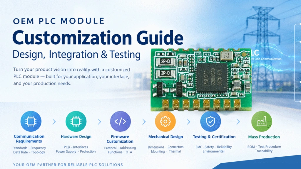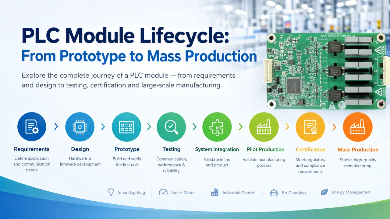
Developing a PLC communication module is more than designing a circuit board and verifying that two devices can communicate. For OEM and ODM projects, the complete PLC module lifecycle typically includes requirements definition, hardware and firmware development, prototype testing, system integration, pilot production, certification, and mass production.
A well-controlled development process helps manufacturers reduce communication problems, hardware redesigns, production defects, and delays when moving from engineering samples to large-scale manufacturing.
This guide explains the typical PLC module lifecycle from prototype to mass production and highlights the key engineering checkpoints at each stage.
What Is the PLC Module Development Lifecycle?
The PLC module development lifecycle is the process of turning a PLC communication concept into a tested, manufacturable product.
A typical lifecycle includes:
Requirements → Architecture → Prototype → Hardware/Firmware Testing → System Integration → Engineering Validation → Pilot Production → Certification → Mass Production → Continuous Improvement
For an OEM PLC project, the exact process may vary depending on the application, communication standard, operating environment, production volume, and certification requirements.
PLC Module Lifecycle at a Glance
| Stage | Main Objective | Typical Output |
|---|---|---|
| 1. Requirements | Define application and communication requirements | Product specification |
| 2. Architecture | Select PLC technology and hardware architecture | System architecture |
| 3. Prototype | Build the first functional hardware | Engineering prototype |
| 4. Firmware Development | Implement communication and control functions | Firmware |
| 5. Functional Testing | Verify electrical and PLC communication performance | Test results |
| 6. System Integration | Test the module inside the customer’s product | Integrated prototype |
| 7. Engineering Validation | Verify reliability and environmental performance | EVT/DVT results |
| 8. Pilot Production | Validate manufacturing process | Pilot batch |
| 9. Certification | Complete required regulatory testing | Certification reports |
| 10. Mass Production | Manufacture products at scale | Production units |
| 11. Maintenance | Improve hardware, firmware, and production quality | Product revisions |
1. Define PLC Module Requirements
The first stage is to clearly define what the PLC module needs to accomplish. Before you start, you can first see this article PLC Module Design Checklist for OEM Development | Hardware & Testing.
A PLC module may be integrated into a lighting controller, industrial controller, smart meter, EV charging device, energy management system, or another electrical product. Therefore, requirements should be defined from both the communication perspective and the host-product perspective.
Important requirements include:
- PLC communication standard
- CCO/STA architecture
- Communication speed
- Communication distance
- Network topology
- Number of nodes
- Operating voltage
- Power consumption
- Host MCU interface
- UART, SPI, PWM, GPIO, ADC, or other interfaces
- Firmware requirements
- Network discovery and commissioning
- Data transmission requirements
- Environmental conditions
- EMC requirements
- Product dimensions
- Connector requirements
- Operating temperature
- Expected production volume
- Target manufacturing cost
For example, an industrial lighting controller may require a compact PLC module with UART communication to the host MCU, while a smart meter may require a different PLC communication architecture and interface.
The most important objective at this stage is to define the complete system requirement before hardware development begins.
2. Select the PLC Architecture
After requirements are established, engineers select the appropriate PLC architecture.
A typical embedded PLC module may contain:
- PLC communication chipset or processor
- MCU/DSP
- Analog front end
- Line driver
- Coupling circuit
- Power supply
- Protection circuit
- Communication interfaces
- Crystal or clock circuit
- Firmware
- Host-product interface
The architecture should consider not only communication performance but also the final product’s electrical environment.
For example, power-line communication can be affected by:
- Electrical noise
- Switching power supplies
- Motor loads
- LED drivers
- Long power lines
- Transformers
- EMI
- Surge events
- Different line impedances
Therefore, the PLC communication module should be designed for the actual application environment rather than evaluated only under laboratory conditions.
3. Develop the First PLC Module Prototype
Once the architecture is confirmed, the engineering team can begin schematic design and PCB development.
The first prototype normally focuses on proving that the fundamental design works.
Typical prototype activities include:
- Schematic design
- PCB layout
- Component selection
- PCB manufacturing
- SMT assembly
- Initial hardware debugging
- Firmware loading
- Basic PLC communication testing
At this stage, engineers should verify fundamental functions such as:
- Module power-up
- Host MCU communication
- PLC transmission
- PLC reception
- Network discovery
- Node addressing
- Data integrity
- Communication stability
The first prototype does not necessarily represent the final mass-production design. Its primary purpose is to identify major hardware, firmware, and architecture issues as early as possible.
4. Develop and Optimize PLC Firmware
Hardware alone does not determine PLC module performance. Firmware is also an important part of the development lifecycle.
Depending on the PLC platform and application, firmware may control:
- PLC communication
- Network discovery
- Node management
- Data processing
- UART/SPI communication
- GPIO control
- Configuration parameters
- Error handling
- Communication retry mechanisms
- Device status
- Diagnostics
- Firmware upgrades
For OEM applications, firmware may also need to communicate with the customer’s existing MCU or application software.
A well-defined host interface is particularly important when the PLC module is integrated into an existing electrical product.
For example:
Host MCU → UART/SPI → PLC Module → PLC Network → Gateway/CCO
This architecture allows the PLC module to provide communication functionality without requiring the customer to redesign the entire control system.
5. Perform PLC Communication Testing
After the prototype is assembled and firmware is available, engineers should conduct structured communication testing. If you are a new user, How to Test a PLC Module Before Mass Production this article is helpful for you.
Basic testing may include:
Communication Distance
Test communication at different cable lengths and under realistic electrical conditions.
Communication Speed
Measure actual data throughput and determine whether the module meets application requirements.
Network Capacity
Test how many PLC nodes can communicate reliably with the intended CCO or gateway.
Packet Loss
Monitor communication reliability during continuous data transmission.
Network Discovery
Verify how quickly PLC nodes can join and establish communication with the network.
Electrical Noise
Test communication when other electrical equipment is operating on the same power network.
Restart and Recovery
Turn devices on and off repeatedly and verify whether the PLC network can recover correctly.
Testing should gradually move from controlled laboratory conditions to the actual electrical environment of the target application.
6. Integrate the PLC Module Into the Customer’s Product
A PLC module may work correctly as an independent development board but encounter new problems after integration. How to Add PLC Communication to Existing Electrical Products this article will show you a guide before starting.
This is why system-level integration testing is a critical stage.
For example, if the PLC module is integrated into an LED lighting controller, engineers should test the complete system:
PLC Module + MCU + LED Driver + Power Supply + Luminaire + Power Line
Potential integration issues include:
- Power supply noise
- EMI generated by the LED driver
- Insufficient isolation
- Incorrect UART settings
- Timing conflicts
- PCB layout problems
- Thermal issues
- Mechanical interference
- Incompatible operating voltage
This stage is particularly important for OEM projects because the final PLC module often needs to operate inside an existing product rather than as a standalone device.
7. Engineering Validation and Design Optimization
After system integration, the design should undergo engineering validation.
The purpose is to determine whether the prototype is sufficiently stable for a production-oriented design.
Typical validation areas include:
Electrical Validation
- Input voltage range
- Power consumption
- Interface voltage levels
- Current consumption
- Protection performance
Communication Validation
- Distance
- Throughput
- Packet loss
- Network stability
- Node capacity
- Recovery after communication interruption
Environmental Validation
- High temperature
- Low temperature
- Temperature cycling
- Humidity
- Long-duration operation
EMC Validation
- Conducted emissions
- Radiated emissions
- Immunity
- Surge
- Electrical fast transient testing
- Electrostatic discharge
The exact tests depend on the final product, target market, and applicable standards. You can follow IEEE 1901 for reference.
8. Optimize the PLC Module for Manufacturing
A prototype that works correctly is not automatically ready for mass production.
Before entering production, engineers should review the design for Design for Manufacturing (DFM) and Design for Testing (DFT).
Important considerations include:
- Component availability
- Component lifecycle
- PCB manufacturability
- SMT placement
- Soldering reliability
- Connector assembly
- Test points
- Programming interfaces
- Automated testing
- Production calibration
- Firmware programming
- Functional testing
- Assembly cost
For example, a prototype may use a component that is easy to obtain in small quantities but difficult to source consistently at large production volumes.
Therefore, component availability and supply-chain stability should be considered before mass production.
9. Build a Pilot Production Batch
Pilot production is the bridge between engineering development and mass production.
Instead of immediately producing tens of thousands of units, manufacturers normally produce a smaller batch to validate the complete manufacturing process.
The pilot batch can be used to evaluate:
- PCB assembly
- Component placement
- Soldering quality
- Firmware programming
- Functional testing
- PLC communication testing
- Production yield
- Assembly time
- Test equipment
- Packaging
- Production documentation
The goal is not simply to determine whether individual units work. It is to determine whether the manufacturing process can repeatedly produce stable units.
10. Complete Certification and Compliance Testing
Depending on the application and target market, the final PLC module or integrated product may require regulatory or customer-specific testing.
Potential requirements may include:
- EMC
- Safety
- Environmental compliance
- RoHS
- REACH
- CE-related requirements
- FCC-related requirements
- Customer-specific standards
Certification requirements vary depending on the final product, country, application, and system architecture.
For an embedded PLC module, certification may sometimes need to be evaluated together with the final host product because the module’s actual operating environment depends on the host device.
Therefore, certification requirements should be considered early in the development process, rather than after the hardware has already been finalized.
11. Release the PLC Module for Mass Production
After prototype validation, system testing, pilot production, and required compliance work are completed, the product can enter mass production.
Before production release, the manufacturer should establish controlled documentation such as:
- Final schematic
- PCB Gerber files
- Bill of materials
- PCB assembly files
- Firmware version
- Programming procedure
- Test specification
- Inspection standard
- Production process
- Quality-control procedure
- Packaging specification
- Product revision number
A production test procedure should also be established.
A typical PLC module production test may include:
Power-On Test → Interface Test → Firmware Test → PLC Communication Test → Parameter Test → Final Inspection
Automated testing can help improve production consistency when production volume becomes large.
12. Monitor Quality After Mass Production
The PLC module lifecycle does not end when mass production begins.
After launch, manufacturers should continue monitoring:
- Field failures
- Communication problems
- Component availability
- Firmware issues
- Customer feedback
- Production yield
- Return rates
- Environmental performance
- New certification requirements
If necessary, the PLC module can be updated through a controlled hardware or firmware revision.
For OEM products, revision control is particularly important. Changes to the PLC chipset, line driver, power supply, PCB layout, or firmware can affect communication performance and should therefore be validated before implementation.
Prototype vs. Mass-Production PLC Module
The engineering priorities are different at different stages.
| Area | Prototype | Mass Production |
|---|---|---|
| Main Goal | Prove the concept | Produce consistently |
| Hardware | Flexible | Fully optimized |
| Components | Engineering selection | Supply-chain validated |
| Firmware | Under development | Controlled release |
| Testing | Engineering testing | Standardized production testing |
| PCB | May require revisions | Fixed production design |
| Manufacturing | Manual/low volume | Automated/high volume |
| Documentation | Development documents | Controlled production documents |
| Cost | Less important | Critical |
| Quality | Function verification | Repeatability and yield |
A successful transition from prototype to mass production requires both technical validation and manufacturing validation.
Common Problems When Moving a PLC Module Into Mass Production
Several problems can occur when a PLC communication module moves from engineering samples to production. PLC Module Not Communicating? 10 Common Problems & Fixes this article will show you more details.
1. Communication Works in the Lab but Not in the Field
The laboratory environment may have less electrical noise than the actual installation.
Solution: Test the module with the real power supply, electrical loads, cable length, and application environment.
2. Prototype Components Become Difficult to Source
A component selected during development may later become expensive, obsolete, or difficult to purchase.
Solution: Review component lifecycle and supply availability before production release.
3. Production Yield Is Too Low
A prototype may work when manually assembled but show inconsistent performance during automated production.
Solution: Introduce production test procedures and review PCB, SMT, component tolerances, and manufacturing processes.
4. PLC Performance Changes After PCB Revision
Changes to PCB layout, coupling circuits, grounding, or power supply components can affect PLC communication.
Solution: Treat important hardware changes as engineering revisions and repeat communication and EMC validation.
5. Firmware Versions Become Difficult to Control
Different production batches may accidentally use different firmware versions.
Solution: Establish firmware version control and production programming procedures.
6. The PLC Module Works, but the Complete Product Does Not
The PLC module may pass standalone testing but fail when integrated into the customer’s power supply, controller, driver, or electrical system.
Solution: Perform system-level validation before mass production.
How Long Does PLC Module Development Take?
The development time depends heavily on whether the project uses an existing PLC module or requires a completely customized design.
A typical project may include:
Requirements: 1–4 weeks
Architecture and hardware design: 2–8 weeks
Prototype: 3–8 weeks
Firmware and communication development: 4–12+ weeks
System integration: 2–8 weeks
Engineering validation: 2–8 weeks
Pilot production: 2–6 weeks
Certification: Project-dependent
Mass production: After final approval
These are general development ranges rather than fixed schedules. Projects involving a new PLC architecture, customized chipset, new communication protocol, special mechanical requirements, or extensive certification can require substantially more time.
Using an existing, field-tested PLC module platform can reduce development work compared with developing a completely new PLC communication architecture.
How to Reduce PLC Module Development Time
OEM companies can shorten the development cycle by separating reusable PLC communication technology from the application-specific product design.
For example, instead of developing the entire PLC communication system from scratch, a company can integrate a pre-developed PLC module into its own controller.
The development process can then focus on:
- Host MCU integration
- Product-specific firmware
- Mechanical integration
- Electrical compatibility
- Application software
- System testing
This approach can reduce the amount of PLC hardware development required while still allowing customization of the final product.
When Should You Choose a Custom PLC Module?
A standard PLC module may be sufficient when:
- The interface requirements are standard
- The module dimensions fit the product
- Existing firmware functions are sufficient
- Communication performance meets requirements
- The target application does not require special hardware
A customized PLC module may be appropriate when you need:
- Custom PCB dimensions
- Custom connectors
- Special operating voltage
- Customized host interfaces
- Special firmware
- Custom PLC protocols
- Different communication parameters
- Integration with an existing controller
- High-volume cost optimization
- Application-specific EMC optimization
For high-volume OEM projects, customization can also allow the module to be optimized for the customer’s PCB, mechanical structure, production process, and target cost.
PLC Module Lifecycle Checklist
Before moving from prototype to mass production, confirm the following:
Requirements
- PLC communication requirements defined
- Operating voltage confirmed
- Host interface confirmed
- Communication distance tested
- Network capacity defined
- Environmental requirements defined
Hardware
- Schematic validated
- PCB validated
- Components selected for production
- Power supply tested
- PLC coupling circuit tested
- Protection circuit validated
- DFM review completed
Firmware
- Communication firmware validated
- Host interface tested
- Network management tested
- Error recovery tested
- Firmware version controlled
- Upgrade procedure defined
System
- PLC module integrated into final product
- Real-world electrical environment tested
- EMI/EMC evaluated
- Temperature testing completed
- Long-duration testing completed
Production
- Pilot production completed
- Production test procedure established
- Programming procedure established
- Production yield evaluated
- BOM and production documents released
- Quality-control procedure established