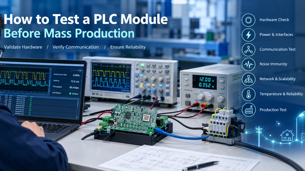
A PLC module may communicate successfully on a laboratory bench and still fail when integrated into a lighting controller, industrial device, or smart meter. Differences in power-line impedance, electrical noise, firmware, temperature, and manufacturing tolerances can expose problems that are not visible during basic functional testing. For the testing standard, can consider IEC for reference.
The goal of pre-production testing is not simply to prove that a PLC module communicates. It is to demonstrate that the complete design communicates reliably, survives its intended operating conditions, and can be manufactured consistently.
This guide explains how to test a PLC module before mass production, from initial hardware inspection to system-level validation and production test planning.
What Should Be Tested Before Mass Production?
A complete PLC module validation program should cover five areas:
Hardware
Power, interfaces, clock, and component behavior.
Communication
Link establishment, data integrity, and network performance.
Electrical
Noise, transients, impedance, and power-line conditions.
Reliability
Temperature, long-duration operation, and environmental stress.
Production
Repeatable testing, traceability, and manufacturing yield.
1. Define the Test Requirements First
Before testing the module, document what “pass” means for the intended application.
For a PLC lighting controller, this may include:
- Operating voltage and current range
- Supported communication protocol and data rate
- Required communication distance
- Maximum number of nodes or network size
- Acceptable packet-error rate
- Startup and network-discovery time
- Required response time
- Operating temperature range
- Protection and isolation requirements
- Expected power-line noise conditions
- Firmware version and configuration
Do not use a single communication-distance result as the only acceptance criterion. A module that reaches a long distance under one laboratory condition may not meet the requirements of a real lighting network.
Example acceptance criteria
| Test item | Example requirement |
|---|---|
| Power supply | Operates across the specified voltage range |
| UART communication | No unexpected data loss at the required baud rate |
| PLC link | Stable communication under defined test conditions |
| Packet error rate | Within the project’s specified limit |
| Network discovery | Meets the required startup time |
| Temperature | Operates without abnormal reset or communication failure |
| Long-duration test | No unexplained communication interruption |
| Production test | Repeatable pass/fail result |
These are example categories, not universal limits. The actual values should come from the module datasheet and the final product requirements.
2. Inspect the Hardware Before Applying Power
The first test is a visual and electrical inspection of the assembled module or evaluation board.
Check the following
- Component placement and orientation
- Solder joints and solder bridges
- Connector pin assignments
- Power and ground connections
- Crystal or oscillator installation
- Coupling circuit components
- Protection components
- PCB traces around high-voltage or noisy sections
- Programming and debugging interfaces
- Manufacturing revision and component substitutions
For a power-line communication design, the coupling circuit deserves special attention. Incorrect component values, poor layout, or an unsuitable isolation and protection arrangement can prevent the PLC transceiver from working correctly even when the communication IC itself is functional.
Recommended equipment
- Digital multimeter
- Microscope or inspection camera
- Oscilloscope
- Programmable power supply
- ESD-safe workbench
- Schematic and PCB layout
- Assembly drawings and BOM
Important: If the module connects directly to mains, use appropriate isolation, rated test equipment, and qualified personnel. Do not connect an oscilloscope ground clip to a non-isolated mains circuit.
3. Verify Power Supply and Startup Behavior
A PLC module should be tested across its intended supply conditions before communication testing begins.
Test procedure
- Apply the nominal supply voltage.
- Measure the input current at startup and during steady-state operation.
- Check supply voltage at the module pins, not only at the power supply.
- Repeat the test at the minimum and maximum specified voltages.
- Observe the reset line, clock, and key power rails.
- Confirm that the module starts correctly after power cycling.
What to look for
- Excessive startup current
- Unexpected reset loops
- Voltage dips during transmission
- Abnormal heating
- Clock instability
- Communication failures caused by power-supply variation
A module may appear stable when idle but fail when the PLC transmitter is active. Therefore, measure the power rail during actual communication, not only during standby.
4. Test the Host Interface
Most embedded PLC modules communicate with a host controller through an interface such as UART, SPI, GPIO, or another supported interface.
For example, a lighting controller may use UART to send commands to the PLC module and receive communication status or data.
Host-interface checklist
- Confirm the pinout and voltage levels.
- Verify the baud rate and communication format.
- Test transmit and receive data.
- Check reset and boot behavior.
- Verify configuration commands.
- Test invalid commands and error responses.
- Confirm that the host can detect communication loss.
- Check whether the module retains or restores its configuration after restart.
Example test
Send a sequence of known commands from the host MCU and verify that the module returns the expected responses.
Host MCU → PLC Module → Power Line → PLC Module → Host MCUThe test should include both normal operation and abnormal conditions, such as incomplete frames, incorrect checksums, and unexpected resets.
5. Test Basic PLC Communication
Once the hardware and host interface are stable, test the PLC communication link.
Minimum communication tests
- Point-to-point communication Verify that two modules can exchange data.
- Bidirectional communication Confirm that both sides can transmit and receive.
- Repeated packet transmission Send a large number of packets and record errors.
- Different packet sizes Test short commands and larger data frames.
- Different transmission intervals Check whether the link remains stable under continuous traffic.
- Power-cycle recovery Confirm that communication resumes after a restart.
Key measurements
| Metric | Why it matters |
|---|---|
| Packet-error rate | Measures data integrity |
| Retransmission count | Shows link stability |
| Latency | Important for control response |
| Throughput | Determines usable data capacity |
| Startup time | Affects network availability |
| Recovery time | Shows behavior after interruption |
A successful ping or command-response test is only the beginning. Reliable PLC communication requires testing under the conditions the final product will actually experience.
6. Test the Coupling Circuit and Power-Line Conditions
The PLC module does not communicate in isolation. Its performance depends on the power-line environment and the coupling circuit connecting the transceiver to the line. PLC Coupling Circuit Design Guide for Embedded PLC Devices this article may better to help you understand more.
This is especially important for lighting systems because LED drivers, switching power supplies, dimmers, and other equipment can introduce electrical noise.
Test different line conditions
- Short and long cable lengths
- Different cable types
- Different loads
- Different power-line impedance
- Different supply voltages
- Different numbers of connected devices
- Different combinations of lighting drivers
- Normal and abnormal operating conditions
Why this matters
A module may work well on a simple test bench but lose communication when connected to a real lighting load. For example, an LED driver may introduce noise during startup or dimming, while a long cable may change the signal conditions.
The coupling circuit, module, and connected load should be tested together whenever possible.
7. Test Communication Under Electrical Noise
Noise immunity is one of the most important parts of PLC module validation. While testing If you meet PLC Module Not Communicating? 10 Common Problems & Fixes, this article may help you to solve the problem better.
Typical noise sources
- LED drivers
- Switching power supplies
- Motors
- Variable-frequency drives
- Contactors and relays
- Dimmers
- Industrial equipment
- Power-line switching events
Recommended test approach
Create a controlled test setup that includes the module, the intended load, and representative noise sources.
Then test communication while:
- Turning loads on and off
- Changing dimming levels
- Starting and stopping motors
- Switching power supplies
- Increasing network traffic
- Operating multiple devices simultaneously
Record packet errors, retransmissions, latency, and recovery behavior.
The purpose is not to eliminate every error under every possible condition. It is to verify that the system meets its defined communication requirements and recovers correctly when errors occur.
8. Test Network Discovery and Scalability
For PLC smart lighting systems, a single module may work correctly while a larger network still has problems.
Test the network with increasing numbers of nodes and different cable arrangements.
Example network tests
- Two-node point-to-point communication
- Small network with several nodes
- Larger network with the intended number of devices
- Multiple branches
- Different node distances
- Repeated network discovery
- Node restart and rejoining
- Communication recovery after a temporary interruption
Questions to answer
- How long does network discovery take?
- Can nodes join reliably?
- Does communication remain stable as the network grows?
- Does traffic from one node affect others?
- Can a node recover after a power interruption?
- Does the network behave consistently across repeated tests?
For a smart lighting application, network testing should include the actual communication pattern, such as periodic status reporting, dimming commands, fault alarms, and scheduled control.
9. Test Firmware and Configuration
Hardware validation is incomplete without firmware testing.
Firmware test items
- Firmware version identification
- Boot and reset behavior
- Configuration storage
- Factory reset
- Parameter validation
- Firmware upgrade process
- Error handling
- Watchdog behavior
- Recovery after communication interruption
- Compatibility between firmware and host software
If the module supports multiple communication modes or configuration profiles, test each supported mode separately.
Keep hardware and firmware versions traceable. A communication failure may be caused by a hardware revision, firmware change, or configuration mismatch rather than the PLC module itself.
10. Test Temperature and Long-Duration Reliability
A PLC module should not only work for a few minutes. It should remain stable during extended operation.
Recommended reliability tests
- Continuous communication test
- Repeated power cycling
- Operation at minimum specified temperature
- Operation at maximum specified temperature
- Temperature transition testing
- Extended operation with representative loads
- Repeated network discovery
- Repeated transmission and reception
Monitor during testing
- Communication errors
- Unexpected resets
- Current consumption
- Module temperature
- Packet loss
- Latency changes
- Firmware status
- Abnormal component heating
For industrial lighting, warehouse, tunnel, and power-plant applications, long-duration testing is particularly important because the equipment may operate continuously and be difficult to access after installation.
11. Test EMC, ESD, and Electrical Protection
The exact tests depend on the final product and the applicable standards, but the validation plan should consider:
- Electrostatic discharge
- Electrical fast transients
- Surge conditions
- Conducted disturbances
- Radiated disturbances
- Immunity to switching events
- Protection against incorrect connection
- Power-supply transients
Do not treat a successful laboratory communication test as proof of EMC compliance. Formal compliance testing should be performed using the applicable standards and qualified test equipment.
The PLC module should also be evaluated as part of the final product, because the enclosure, power supply, PCB layout, and connected loads can affect EMC performance.
12. Test Manufacturing Consistency
Before mass production, the design must be tested not only for functionality but also for repeatability.
Production validation should include
- Multiple assembled samples
- Different production batches
- Component tolerance variation
- PCB assembly variation
- Different firmware versions, where applicable
- Repeated power-on and communication tests
- Inspection of critical solder joints
- Verification of programming and configuration
- Final functional test after assembly
Why this matters
A prototype may work because of a favorable component tolerance or a particular assembly condition. A production test should help identify whether the design is robust enough to tolerate normal manufacturing variation.
13. Create a Production Test Plan
A good production test plan separates engineering validation from factory testing.
Engineering validation
Used to prove that the design meets its requirements.
Examples:
- Communication performance
- Noise immunity
- Temperature testing
- Long-duration reliability
- Network scalability
- EMC evaluation
Factory testing
Used to verify that each manufactured unit is functional.
Examples:
- Visual inspection
- Power-on test
- Current consumption
- Firmware programming
- Host-interface test
- Basic PLC communication test
- Configuration verification
- Final functional test
Not every engineering test needs to be repeated on every production unit. The factory test should focus on the critical parameters that can be tested quickly and consistently.
14. Recommended PLC Module Pre-Production Checklist
| Test stage | Main objective | Typical result |
|---|---|---|
| Visual inspection | Detect assembly defects | Pass / Fail |
| Power test | Verify supply and startup | Measured voltage/current |
| Host interface | Confirm MCU communication | Pass / Fail |
| Basic PLC link | Verify communication | Packet-error rate |
| Coupling test | Confirm line connection | Communication stability |
| Noise test | Verify immunity | Error/recovery data |
| Network test | Verify scalability | Discovery and recovery time |
| Firmware test | Confirm configuration and recovery | Pass / Fail |
| Temperature test | Verify operating range | Stability data |
| Reliability test | Verify long-duration operation | Error and reset log |
| Production test | Verify manufacturing consistency | Yield and failure data |
15. Common Mistakes to Avoid
Mistake 1: Testing only on a clean laboratory bench
A clean test setup may not represent the electrical environment of the final product.
Better approach: Include representative loads, cables, and noise sources.
Mistake 2: Testing only one module pair
A point-to-point test does not prove that a larger network will work reliably.
Better approach: Test the intended network size and communication pattern.
Mistake 3: Measuring only communication distance
Distance alone does not describe communication quality.
Better approach: Record packet errors, retransmissions, latency, and recovery behavior.
Mistake 4: Ignoring the power supply
A module may reset or lose communication when the transmitter is active.
Better approach: Measure the supply during real communication and load operation.
Mistake 5: Treating firmware as separate from hardware
A hardware revision may require firmware changes, and configuration errors can appear as communication failures.
Better approach: Record the exact hardware revision, firmware version, and test configuration.
Mistake 6: Waiting until mass production to define factory tests
Without a production test plan, manufacturing defects may be difficult to identify consistently.
Better approach: Define the production test method during the engineering validation stage.
16. Example Test Setup for a PLC Lighting Controller
A practical test setup may include:
Host MCU
PLC Module
Coupling Circuit
Power Line / Representative Load
PLC Module
Host MCU
The setup should allow engineers to observe communication behavior while changing line conditions, loads, and network traffic.
17. How MicroNature Can Support PLC Module Validation
For embedded PLC applications, the validation process should consider both the communication module and the final system design.
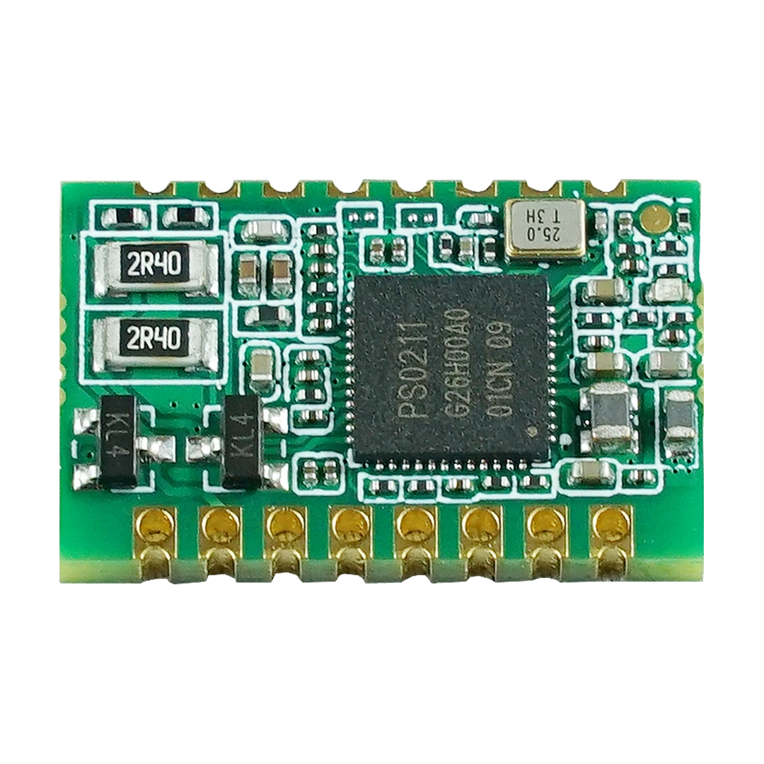
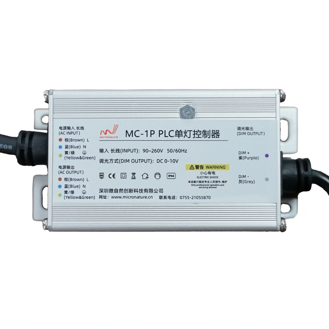
MicroNature provides PLC communication modules for embedded applications, including the MN-L80C and other PLC module solutions. Depending on the project, validation may include host-interface integration, coupling circuit design, communication testing, and system-level testing.
For a module evaluation, engineers should confirm the exact electrical specifications, supported interfaces, communication protocol, and recommended application circuit from the relevant product documentation.
Suggested internal links:
- PLC module overview →
/products/ - MN-L80C PLC module → Use the exact product-page URL from your catalog.
- PLC Coupling Circuit Design Guide → Link to your published coupling article.
- PLC Module vs PLC Chipset vs PLC Board → Link to your existing comparison article.
- PLC Network Capacity Calculation Guide → Link to your published network-capacity article.
- PLC Module Not Communicating? 10 Common Problems → Link to your troubleshooting article.