
The performance of a Power Line Communication (PLC) module depends on more than its advertised data rate. For engineers developing smart lighting controllers, industrial equipment, smart meters, and other connected electrical products, three factors are especially important: data rate, communication range, and network capacity.
Data rate determines how quickly information can be transmitted. Communication range describes how far signals can travel reliably over an electrical network. Network capacity determines how many devices and how much communication traffic a system can support while meeting its response-time and reliability requirements.
These factors are closely related. A PLC module may support a high physical-layer data rate, but actual application throughput can be lower because of protocol overhead, retransmissions, electrical noise, and competing devices. Similarly, a signal that works well across a short laboratory connection may perform differently on a long power line connected to multiple LED drivers.
For OEM engineers and smart lighting system integrators, understanding these differences is essential when selecting a power line communication module and designing a reliable network.
This guide explains how PLC module performance is measured, which factors influence real-world results, and how to evaluate a PLC solution for your application.
1. What Determines PLC Module Performance?
PLC technology transmits digital information over existing electrical conductors. Unlike wireless communication, which uses radio waves through the air, PLC uses the power-line network as its communication medium.
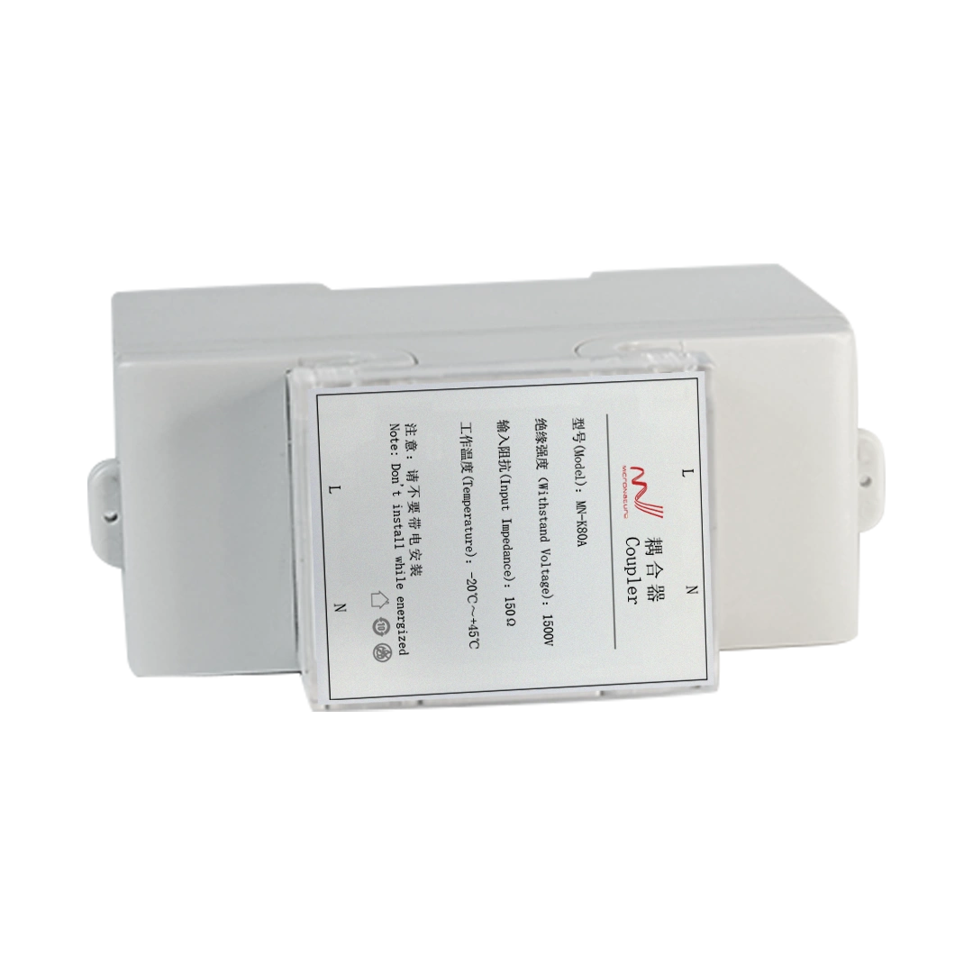
A typical PLC system may include a central controller or gateway, PLC communication modules integrated into endpoint devices, and a coupling circuit that connects the communication electronics to the power line.
The main performance indicators include:
| Performance indicator | What it means | Why it matters |
|---|---|---|
| Physical-layer data rate | The signaling rate supported by the PLC PHY | Indicates the theoretical communication capability |
| Application throughput | The useful data delivered to the application per unit of time | Determines practical data-transfer performance |
| Communication range | The distance over which communication remains reliable | Influences network coverage and topology |
| Network capacity | The number of devices and traffic load the network can support | Determines system scalability |
| Latency | The time required for a message to reach its destination | Affects control response and monitoring |
| Packet delivery reliability | The proportion of messages successfully delivered | Influences control stability and data completeness |
These indicators should be evaluated together. Selecting a module based only on its maximum data rate or maximum communication distance may lead to an unsuitable system design.
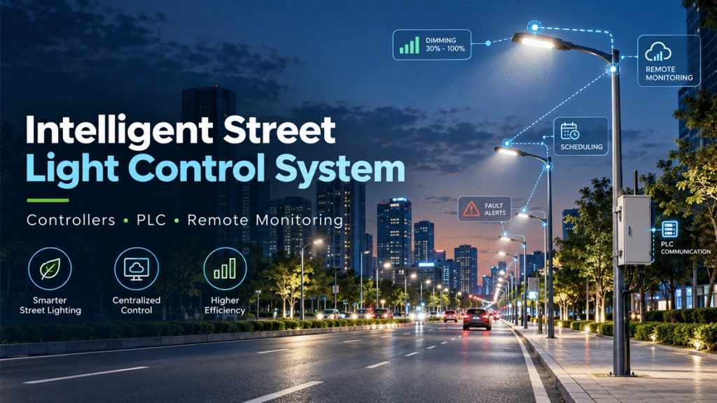
For example, a smart street lighting network may prioritize reliable commands, device status reporting, and fault alarms rather than continuous high-bandwidth data transmission. An industrial application with frequent measurements or firmware updates may have different requirements.
2. PLC Module Data Rate: PHY Rate vs. Actual Throughput
2.1 What is PLC data rate?
PLC data rate describes how quickly information can be transmitted through the power-line communication channel. It is commonly expressed in bits per second (bps), kilobits per second (kbps), or megabits per second (Mbps). For more information, you can see our article PLC Module Reference Design: Hardware, Interfaces and Power-Line Coupling. For PLC systems based on medium-frequency power-line communication, IEEE 1901.1-2018 specifies physical-layer and medium-access-control requirements for smart-grid applications, including OFDM-based communication.
However, two different figures should be distinguished:
- Physical-layer data rate: The rate supported by the communication PHY under a particular configuration and channel condition.
- Application throughput: The rate at which useful application data is successfully delivered after accounting for protocol overhead, access delays, acknowledgments, retransmissions, and other network activities.
The actual throughput is generally lower than the PHY rate.
For example, a module with a nominal PHY rate of 500 kbps should not automatically be expected to deliver 500 kbps of application data continuously. The effective rate must be measured using the intended protocol, network topology, and electrical environment.
2.2 What affects PLC communication speed?
Several factors influence the actual data rate and throughput of a PLC network.
Modulation and coding
PLC technologies may use modulation methods such as OFDM, FSK, PSK, or QAM, depending on the design and standard. The selected method, coding configuration, and channel conditions influence the achievable rate and robustness.
Signal-to-noise ratio
Electrical noise reduces the receiver’s ability to distinguish the intended signal from interference. When the channel becomes less reliable, communication may require more robust transmission settings or additional retransmissions.
Protocol overhead
Network discovery, addressing, acknowledgments, routing, and error recovery consume communication resources. These activities are necessary for reliable networking but reduce the portion of the channel available for application data.
Network traffic
When many devices share the same communication medium, they may need to compete for transmission opportunities. As traffic increases, waiting time and message collisions or retries may increase, depending on the protocol.
Message size and frequency
Small control commands have different overhead characteristics from large data transfers. A network sending frequent short messages may achieve a different effective throughput from a network transferring larger data blocks.
2.3 How much data rate does a smart lighting system need?
The required rate depends on the application rather than the module specification alone.
| Application | Typical communication requirements |
|---|---|
| Street lighting control | Switching, dimming, schedules, status reporting, and fault alarms |
| Industrial lighting | Lighting commands, sensor reports, equipment status, and automation integration |
| Smart metering | Meter readings, configuration, event reports, and data collection |
| Distributed control systems | Periodic measurements, commands, alarms, and device coordination |
| Firmware and configuration updates | Larger data transfers that may require additional bandwidth and time |
For a lighting system, control messages may be relatively small, but a large deployment can generate substantial aggregate traffic when many devices report their status at the same time.
Engineering recommendation: Evaluate the expected traffic per device, reporting frequency, message size, protocol overhead, and peak simultaneous activity. Then measure application throughput under realistic network conditions.
3. PLC Communication Range: How Far Can a Signal Travel?
3.1 Why PLC communication distance varies
There is no single communication distance that applies to every PLC module or electrical installation.
A PLC signal travels through an electrical network whose characteristics may vary significantly between projects. Cable length is important, but it is not the only factor determining communication range.
Important factors include:
- Cable characteristics: Cable type, conductor size, impedance, and frequency-dependent attenuation affect signal propagation.
- Electrical topology: Branch circuits, junctions, transformers, and changes in wiring configuration may affect signal paths.
- Connected loads: LED drivers, switching power supplies, motors, and other electronic equipment may introduce noise or alter the communication channel.
- Coupling circuit design: The coupling network must transfer the PLC signal effectively while meeting electrical safety and hardware requirements.
- Signal attenuation: Signal strength decreases as the communication path introduces losses.
- Electrical noise and interference: Noise can reduce the available communication margin and increase packet errors.
- Network architecture: Repeaters, routers, or intermediate devices may extend the communication path when supported by the selected protocol.
Consequently, a PLC module that performs reliably on one installation may require a different topology or additional engineering work on another.
3.2 Is PLC communication range the same as cable length?
No. Cable length and communication range are related, but they are not equivalent.
A long cable with relatively low attenuation and limited interference may provide a more favorable communication channel than a shorter cable connected to noisy electronic loads.
For this reason, engineers should avoid treating a maximum distance published for a particular test setup as a guaranteed distance for every installation.
A meaningful range specification should identify the test conditions, including the cable type, line configuration, connected loads, network topology, data rate, and required packet delivery performance.
3.3 How to improve PLC communication range
The following design practices can help improve communication reliability over longer power-line networks.
1. Optimize the coupling circuit.
Review coupling component values, impedance matching, signal injection, and the frequency response of the coupling path. The circuit must also satisfy the applicable isolation, safety, surge, and EMC requirements.
2. Reduce the effects of electrical noise.
Identify noisy loads and interference sources. Test the network with the actual LED drivers, switching power supplies, and other connected equipment rather than evaluating the PLC module in isolation.
3. Evaluate the network topology.
Identify long branches, heavily loaded sections, and locations where signal attenuation is significant. Test representative paths before finalizing the installation design.
4. Use supported relays or repeaters where necessary.
Some PLC architectures support multi-hop communication. Intermediate devices can forward messages through the network, extending the logical communication path. However, every additional hop may increase latency and consume network resources.
5. Validate the complete system.
Test communication under normal operation, peak load, switching events, and other relevant electrical conditions. Measure packet delivery, retries, latency, and disconnection frequency.
The objective is not simply to make the signal travel farther. It is to achieve reliable communication across the intended network.
4. PLC Network Capacity: How Many Devices Can One Network Support?
4.1 Understanding network capacity
PLC network capacity is the ability of a communication system to support a given number of devices and their combined traffic while maintaining acceptable reliability, latency, and control performance.
It is not determined by the number of addresses supported by the protocol alone.
A network might theoretically identify a large number of devices but still struggle to meet response-time requirements when many devices communicate simultaneously.
Network capacity depends on several factors:
- Maximum supported device count and addressing rules
- Available application throughput
- Communication protocol and network access method
- Number of hops between the controller and endpoints
- Message size and reporting frequency
- Device discovery and network maintenance overhead
- Retransmissions and interference
- Gateway processing capability and backhaul connectivity
- Required command response time and reliability
For this reason, engineers should distinguish maximum addressable devices, successfully networked devices, and devices that can be served under the required traffic and response-time conditions.
These are related but different measurements.
4.2 How to estimate PLC network traffic
A simple first estimate can help identify whether a proposed network requires further capacity testing.
Suppose a system contains 500 PLC endpoints. Each endpoint sends a 100-byte application report every 60 seconds.
The average application payload rate is:
[
R=\frac{N \times S \times 8}{T}
]
Where:
- (R) = average application payload rate in bits per second
- (N) = number of endpoints
- (S) = application report size in bytes
- (T) = reporting interval in seconds
Using the example:
[
R=\frac{500 \times 100 \times 8}{60}
]
[
R\approx 6{,}667\text{ bps}
]
The average application payload rate is approximately 6.67 kbps.
This figure does not include protocol headers, acknowledgments, retransmissions, network management, or other traffic. It also assumes the reports are distributed evenly over time.
If all 500 devices report simultaneously, the network may experience a much higher short-term traffic load, even though the long-term average remains the same.
This is why traffic scheduling and staggered reporting can be important in large PLC networks.
4.3 How to estimate the number of devices a PLC network can support
There is no universal formula that converts a PLC PHY data rate directly into a maximum device count. A useful initial estimate can instead be based on the available application throughput and expected device traffic.
If each device generates an average traffic load of (r) bits per second, and the application has an effective throughput budget of (B), a simplified estimate is:
[
N_{\text{traffic}}\approx\frac{B}{r}
]
For example, if a tested network provides 50 kbps of usable application throughput and each endpoint generates an average of 100 bps:
[
N_{\text{traffic}}\approx\frac{50{,}000}{100}=500
]
This gives a theoretical traffic-based estimate of 500 endpoints. It is not a guarantee that the network can support 500 devices.
The final design must reserve capacity for peak traffic, retries, network management, latency requirements, and other overhead. It must also comply with the protocol’s device-count and topology limits.
For smart lighting, engineers should additionally test group commands, simultaneous status requests, device reconnection, and alarm reporting under realistic deployment conditions.
5. How Network Topology Affects PLC Performance
Network topology influences both the communication path and the resources required to deliver messages.
Common considerations include direct communication between a controller and endpoints, branched power-line networks, and multi-hop or mesh-style architectures where supported by the selected PLC technology. If you are a new user, please select suitable PLC Lighting Solution before project start.
Direct communication
A direct communication path may offer relatively low latency and fewer forwarding overheads. However, its reliability depends on the quality of the electrical path between the controller and endpoint.
Branched power-line networks
Branches allow devices to connect through different sections of an existing electrical installation. The resulting performance depends on cable characteristics, connected loads, and signal propagation through each branch.
Multi-hop or mesh networking
In a multi-hop architecture, intermediate devices forward messages when the protocol supports this function. This can extend network coverage and improve connectivity in some installations.
However, more hops can introduce additional transmission delays and consume shared network resources. The number of supported relay levels should not be confused with the maximum number of devices or the total network throughput.
For example, a PLC lighting controller specification may state that it supports a certain number of relay levels. That figure describes a forwarding or topology capability, not the number of luminaires the entire network can necessarily support.
When evaluating a PLC solution, confirm the maximum supported network size, hop count, discovery behavior, routing method, and performance under the intended traffic load.
6. How to Evaluate PLC Module Performance Before Mass Production
For OEM manufacturers, the best way to evaluate a PLC module is to test the complete communication system under conditions representative of the final product. How to Test a PLC Module Before Mass Production: A Practical Validation Guide this article is better for reference.
A structured test plan should include the following steps.
Step 1: Confirm the module specification
Review the module’s physical-layer data rate, supported protocol, frequency band, modulation methods, interfaces, operating conditions, and network topology capabilities.
Check whether published performance figures represent theoretical PHY capability, laboratory measurements, or application-level results.
Step 2: Test the coupling circuit and PCB
Verify that the coupling circuit, layout, grounding strategy, power supply, and isolation design are appropriate for the intended application.
A module that works when connected to a laptop or shared laboratory ground may behave differently when the controller and endpoint use separate power supplies. Such behavior may indicate an issue involving the coupling path, grounding, noise, or signal reference, and requires systematic testing.
Step 3: Measure communication performance at different distances
Test short, medium, and long representative communication paths. Include different cable configurations and realistic connected loads.
Record packet delivery rate, latency, retransmissions, and disconnections rather than measuring signal presence alone.
Step 4: Increase the number of networked devices
Start with a small network and progressively increase the number of endpoints. Measure command response time, reporting delays, discovery time, and packet delivery reliability as network traffic grows.
Step 5: Test peak traffic
Simulate simultaneous device reports, group commands, alarm events, reconnection after power interruptions, and other relevant peak-load scenarios.
Step 6: Test electrical noise and load switching
Operate the system with representative LED drivers, motors, switching power supplies, dimming conditions, and other expected loads. Test during relevant switching events to identify potential communication problems.
Step 7: Validate long-duration stability
Run the network for an appropriate period and record communication failures, device dropouts, recovery time, and changes in performance.
These tests help determine whether the selected module, coupling circuit, and network architecture meet the application’s real requirements before mass production.
7. Selecting a PLC Communication Module for Smart Lighting
For smart lighting and industrial OEM projects, module selection should consider more than the headline data rate.
Evaluate the following criteria:
| Selection criterion | Questions to ask |
|---|---|
| Communication standard | Which PLC protocol or standard does the module implement? |
| Data rate | What are the supported PHY rates and measured application throughput? |
| Coupling design | Is the coupling circuit integrated or externally designed? |
| Communication range | What cable and load conditions were used to validate the range? |
| Network capacity | How many devices can be supported under the required traffic conditions? |
| Topology | Does the solution support routing, relaying, or mesh networking? |
| Host interfaces | Are UART, SPI, GPIO, or other required interfaces available? |
| Noise immunity | How does the system perform with actual connected electrical loads? |
| Integration | Can the module be integrated into the luminaire driver, controller, or other embedded product? |
| Software support | Are communication APIs, reference designs, configuration tools, and technical support available? |
A suitable PLC module should provide the right balance of data rate, reliable communication, network scalability, integration effort, and total system cost.
For many lighting applications, stable communication across the intended electrical network is more valuable than a high theoretical data rate that cannot be maintained under real operating conditions.
8. PLC Module Performance in MicroNature Smart Lighting Applications
For smart lighting OEMs and system integrators, MicroNature develops PLC communication modules and devices designed to support power-line networking in embedded products and lighting control systems.
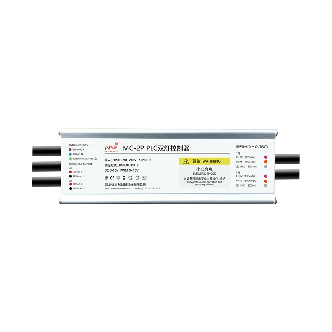
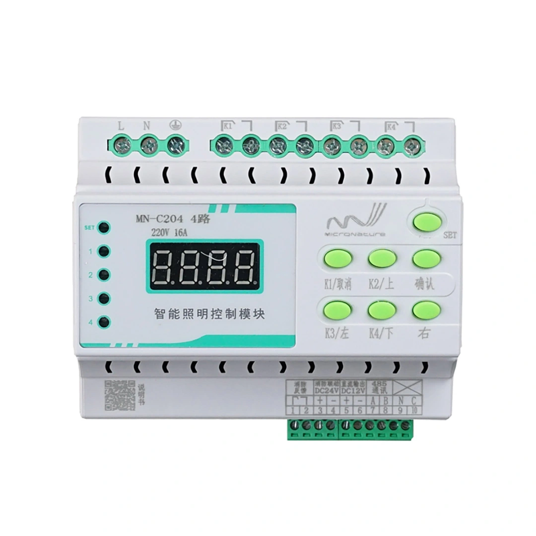
Depending on the selected model and system architecture, the solution can support integration with lighting controllers, gateways, dimming equipment, and centralized management platforms.
For example, the MN-L60C PLC communication module uses an ARM Cortex-M4 and 32-bit DSP architecture and supports PLC communication functions intended for embedded applications. The MN-L80A and MN-L80C product family uses the PS0211 platform and supports PLC communication based on IEEE P1901.1-related technology.
Actual data rate, network capacity, interfaces, and system capabilities must be confirmed against the specification of the selected model and its firmware configuration. They should not be assumed to be identical across the product family.
When developing a PLC-based smart lighting system, engineers should evaluate the module together with the coupling circuit, host controller, power supply, connected electrical loads, and network architecture.
This system-level approach helps OEMs determine whether the proposed solution meets their required communication range, device count, response time, and reliability.
If you are developing a PLC-based lighting controller or integrating power line communication into an existing electrical product, consult the relevant module datasheet and reference design before finalizing the hardware architecture.