Integrating Power Line Communication (PLC) into an electronic product requires more than selecting a communication chip or module. Engineers must consider the host controller, communication interfaces, power supply, power-line coupling circuit, electrical protection, electromagnetic compatibility (EMC), and the characteristics of the target power network.
A well-designed PLC module reference design helps OEM manufacturers shorten development time, reduce hardware integration risks, and build reliable communication into lighting controllers, industrial equipment, smart meters, energy management systems, and other connected devices.
Unlike communication technologies that require dedicated data cables or separate radio links, PLC transmits data over existing electrical conductors. This can reduce additional communication wiring in suitable applications, but it also introduces specific challenges related to electrical noise, impedance, isolation, and power-line safety.
This guide explains the main hardware blocks of a PLC module reference design, how common host interfaces work, how power-line coupling fits into the system, and what OEM engineers should verify before moving from prototype development to mass production.
1. What Is a PLC Module Reference Design?
A PLC module reference design is a hardware and integration framework showing how a Power Line Communication module connects to a host controller and communicates through an electrical power line.
Depending on the product architecture, a reference design may include:
- A PLC communication module or chipset.
- A host microcontroller (MCU) or embedded processor.
- A UART, SPI, GPIO, or other supported interface.
- A suitable power supply and voltage regulation circuit.
- A power-line coupling and signal-conditioning circuit.
- Surge protection, filtering, and other protection components.
- Firmware, communication protocols, and diagnostic functions.
- Test points and procedures for electrical and communication validation.
The exact implementation depends on the PLC chipset, module design, communication standard, operating voltage, and end application.
For OEM engineers, the objective is not simply to reproduce a circuit. It is to establish a verified hardware architecture that can be adapted to the target product without compromising communication reliability, electrical safety, or manufacturing consistency.
2. Typical PLC Module Hardware Architecture
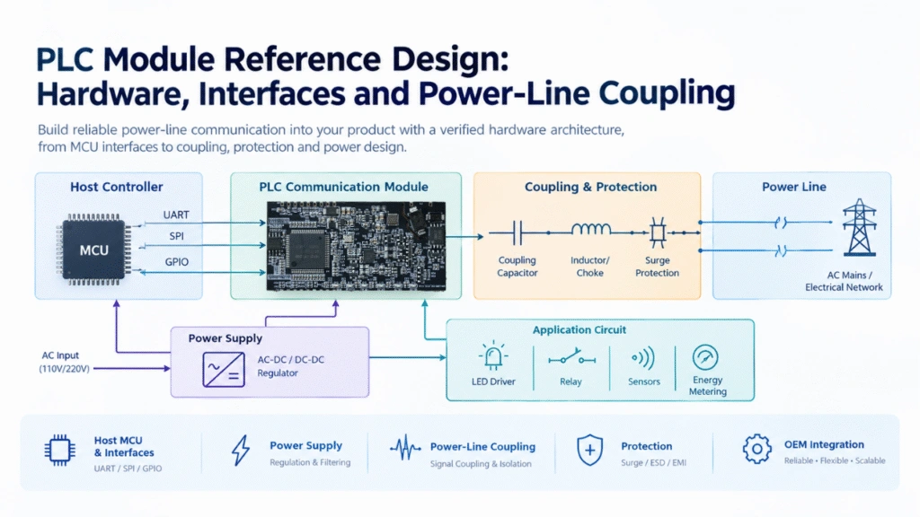
A PLC-enabled product can be divided into several functional blocks.
2.1 Main hardware blocks
PLC communication module: Performs the physical-layer communication functions and, depending on the device, may also provide part of the communication protocol stack.
Host MCU: Manages the application logic, sensor inputs, control outputs, device configuration, and communication with the PLC module.
Host interface: Transfers commands, configuration parameters, and application data between the MCU and PLC module.
Power supply: Provides the regulated voltage and current required by the module and associated electronics.
Power-line coupling circuit: Couples the PLC communication signal onto the electrical network and extracts received signals from the line.
Protection circuit: Helps protect the design against applicable electrical disturbances, including surges, transients, and electrostatic discharge where relevant.
Application circuit: Provides the product-specific functions, such as LED dimming, relay control, energy measurement, sensor acquisition, or industrial equipment monitoring.
2.2 Reference architecture diagram
The following conceptual architecture illustrates the relationship between the main blocks:
Host MCU → Host Interface → PLC Communication Module → Coupling and Protection Network → Power Line
The power supply provides the required operating power to the electronic blocks. Application circuits, such as LED drivers, sensors, relays, or measurement circuits, connect to the host MCU according to the product requirements.
This diagram is a functional overview rather than a complete schematic. The placement of the coupling circuit, power supply, and protection components depends on whether the PLC module integrates the line driver, coupling network, or other analog front-end functions.
2.3 Integrated module versus discrete chipset
There are two common approaches to implementing PLC communication.
Approach A: Use an integrated PLC communication module
A module may integrate the PLC chipset, selected supporting components, and a line driver. Some modules may also include an MCU, power conditioning, or other functions.
Advantages can include a simpler host design, fewer components to integrate, and a more straightforward development process. However, the engineer must verify exactly which functions the module includes.
Approach B: Design around a PLC chipset
A discrete chipset-based design may provide greater flexibility over component selection, PCB layout, coupling circuitry, and system-level integration. It also places more responsibility on the engineering team for RF or analog front-end design, signal integrity, EMC, firmware integration, and validation.
For many OEM projects, a pre-developed PLC module is a practical starting point when its interfaces, electrical ratings, protocol support, and coupling requirements match the target application.
3. Selecting the Host MCU and PLC Interface
The host interface is one of the most important decisions in PLC hardware integration. It determines how the application processor exchanges data and configuration information with the PLC subsystem.
3.1 UART interface
UART is widely used for communication between embedded controllers and external modules.
Typical applications include:
- Sending commands and configuration parameters.
- Receiving communication status and diagnostic information.
- Transferring application data.
- Connecting a PLC module to an MCU with limited interface requirements.
Engineers should verify the supported baud rates, voltage levels, data format, flow-control requirements, packet framing, and error-handling mechanism.
UART is often a practical choice for straightforward module integration, but the actual supported features depend on the selected PLC module and its firmware.
3.2 SPI interface
SPI can provide a higher-throughput synchronous interface when supported by the PLC device.
It may be appropriate for systems that need faster transfers, tighter control over data movement, or integration with an existing SPI-based architecture.
Before choosing SPI, confirm the available interface modes, clock limits, chip-select behavior, timing requirements, driver availability, and firmware support. Not every PLC module exposes SPI, even if the underlying chipset supports it.
3.3 GPIO and control signals
GPIO lines may be used for functions such as:
- Reset and enable control.
- Interrupt or event notification.
- Operating-state indication.
- Hardware handshaking.
- Application-specific digital inputs or outputs.
These signals can simplify device management, but their electrical levels and timing requirements must match the host MCU.
3.4 Choosing an interface
| Design consideration | UART | SPI |
|---|---|---|
| Connection complexity | Generally simple | Requires clock and chip-select signals |
| Communication method | Asynchronous serial | Synchronous serial |
| Potential throughput | Depends on baud rate | Can support higher rates when implemented appropriately |
| Typical integration | Command and data exchange | Higher-throughput host communication |
| Main checks | Baud rate, framing, flow control | Clock, timing, mode, chip select |
| Module support | Must be verified | Must be verified |
The best interface is the one supported by the selected PLC module and suitable for the host processor, data rate, firmware architecture, and product cost target. If you want start develop your own product, OEM PLC Module Customization Guide: Design, Integration & Testing this article is better for you to check.
4. PLC Power-Line Coupling Circuit Design
The power-line coupling circuit is a critical part of PLC hardware because it connects the communication subsystem to the physical transmission medium. Before you start, please first check this article PLC Coupling Circuit Design Guide for Embedded Power Line Communication Devices.
The coupling network must allow the PLC signal to pass between the communication circuit and the electrical line while managing the relevant operating voltage, signal attenuation, impedance characteristics, and electrical safety requirements.
4.1 Main functions of the coupling circuit
A typical coupling network performs several functions:
- Signal coupling: Transfers the communication signal between the PLC front end and the power line.
- Signal isolation or separation: Helps prevent unwanted power-frequency energy from entering sensitive communication circuitry, according to the chosen topology.
- Impedance management: Helps establish suitable signal-transfer characteristics over the intended frequency band.
- Electrical protection: Works with appropriate protective components to address foreseeable electrical transients and faults.
- Noise management: Helps control interference and unwanted coupling between the PLC signal, power electronics, and other circuits.
The exact functions and component arrangement depend on the PLC frequency band, line conditions, coupling method, and the design of the PLC chipset or module.
4.2 Common coupling components
Coupling capacitors: May provide frequency-selective coupling between the communication front end and the power line. Their voltage rating, safety classification, capacitance, and suitability for the circuit must be determined by the application and applicable standards.
Transformers or other isolation components: May be used where the selected architecture requires galvanic isolation or a particular coupling characteristic.
Inductors and chokes: May help shape the frequency response, separate signal paths, or reduce unwanted high-frequency interference. Their characteristics must be evaluated in the actual circuit.
Protection components: Depending on the design, these may include suitable surge protective devices, resistors, fuses, or other components selected for the expected electrical environment.
Filtering components: May be used to reduce unwanted interference or manage interactions with power converters and other circuitry.
These components are not interchangeable across all PLC designs. A component that performs well in one frequency band, line impedance, or coupling topology may not perform adequately in another.
4.3 What determines coupling performance?
Coupling performance depends on several interacting factors:
- PLC operating frequency and signal bandwidth.
- Power-line impedance and cable characteristics.
- Coupling component values and tolerances.
- PCB layout and parasitic capacitance or inductance.
- Conducted noise generated by switching power supplies and LED drivers.
- Protective components and their influence on the signal path.
- Installation topology, cable length, and connected loads.
Consequently, a coupling circuit should be evaluated as part of the complete PLC system, not only through isolated component calculations.
4.4 Isolation and electrical safety
Power-line communication hardware may be connected to hazardous mains voltages. The coupling circuit must therefore be designed according to the product’s voltage category, insulation requirements, pollution degree, overvoltage conditions, applicable safety standards, and intended installation environment.
Do not assume that a capacitor, transformer, or other individual component automatically makes the complete design safe. Creepage distances, clearance distances, insulation coordination, protective-earth arrangements where applicable, enclosure design, and fault conditions must all be considered.
For mains-connected products, use appropriately qualified electrical engineers and complete the required safety evaluation before testing or deploying the hardware. Do not connect an unverified prototype directly to a live power line.
5. Power Supply and PCB Layout Considerations
The PLC module power supply and PCB layout can significantly affect communication stability.
5.1 Power supply requirements
Check the PLC module’s specified input-voltage range, current consumption, startup behavior, transient tolerance, and power sequencing requirements.
The design should also consider:
- Peak current during transmission or startup.
- Voltage drop and regulator thermal performance.
- Decoupling capacitor placement.
- Grounding and return-current paths.
- Noise generated by switching regulators.
- Interaction between the PLC module and nearby power electronics.
A power supply that meets the nominal voltage requirement may still create communication problems if its switching noise enters the PLC receiver or coupling network.
5.2 PCB layout
PCB layout should preserve the intended electrical characteristics of the communication and coupling paths.
Important checks include:
- Keep sensitive analog and communication nodes away from noisy switching nodes.
- Follow the module manufacturer’s recommendations for decoupling and grounding.
- Minimize unintended parasitic coupling.
- Route high-current switching paths carefully.
- Maintain the required isolation boundaries.
- Position protection components according to their function and the intended surge-current path.
- Provide accessible test points where appropriate.
The correct layout depends on the module architecture. An integrated module with a validated line driver may have different layout requirements from a discrete chipset design with an external analog front end.
5.3 Managing interference from power electronics
LED drivers, motor drives, switching power supplies, and other nonlinear loads can introduce conducted noise onto the power line.
In smart lighting, this issue deserves particular attention because the PLC communication system and LED driver may operate within the same luminaire or electrical installation.
Practical validation should include the actual power supply, driver, dimming range, cable arrangement, and expected electrical loads. A design that communicates reliably on a laboratory power source may behave differently when connected to the final installation.
6. Firmware and Protocol Integration
A complete PLC reference design includes more than hardware. Firmware determines how the host MCU initializes the module, configures communication, handles application data, and recovers from communication failures.
Typical software tasks include:
- Module initialization and configuration.
- Command and response handling.
- Data framing and validation.
- Communication timeouts and retry logic.
- Device addressing and network joining.
- Link-status monitoring and diagnostic reporting.
- Firmware update or recovery procedures, where supported.
The host application should distinguish between the status of the local interface and the status of the PLC network. For example, a UART connection may be working correctly even when a remote PLC node is unreachable.
For multi-node networks, the design should also define how the device handles discovery, addressing, network configuration, and reporting of communication failures. These functions depend on the chosen PLC protocol and system architecture.
7. Testing and Validation Before Mass Production
A PLC reference design should be validated under conditions that reflect the intended application. If you are a new user, please first see our article PLC Module Troubleshooting: A Practical Guide for OEM Engineers.
7.1 Hardware checks
Confirm:
- Operating voltages and current consumption.
- Startup and reset behavior.
- Interface timing and signal levels.
- Temperature rise under expected operating conditions.
- Protection-component suitability.
- Isolation and safety requirements.
7.2 Communication checks
Evaluate:
- Successful module initialization.
- Data transmission and reception.
- Packet error rates or other suitable communication-quality metrics.
- Network discovery and joining.
- Performance at different cable lengths and load conditions.
- Communication stability under representative electrical noise.
- Recovery after power interruptions or temporary communication loss.
7.3 System-level checks
For a PLC lighting controller, test the complete combination of the PLC module, host MCU, LED driver, dimming interface, power supply, and representative luminaires.
For industrial equipment, use the intended sensors, actuators, control electronics, and installation wiring.
Where relevant, evaluate surge immunity, conducted emissions, radiated emissions, electrical safety, and environmental performance according to the product’s applicable standards and test plan.
Document the test setup, firmware version, hardware revision, network configuration, and results so that the same performance can be checked during production.
8. Common PLC Reference Design Problems
Problem 1: The host MCU cannot communicate with the PLC module
Possible causes: Incorrect baud rate, mismatched logic levels, incorrect pin assignment, reset timing, or unsupported interface configuration.
Recommended action: Verify the module datasheet, power rails, reset behavior, and interface signals before investigating the power-line network.
Problem 2: The module works on the bench but fails on the actual power line
Possible causes: Electrical noise, different line impedance, unsuitable coupling, or interference from connected equipment.
Recommended action: Reproduce the intended installation conditions and measure communication performance under representative loads and cable configurations.
Problem 3: Communication becomes unstable when the LED driver is dimmed
Possible causes: Switching noise that changes with operating mode, interference from the driver, or interactions between the dimming circuit and PLC signal path.
Recommended action: Test multiple dimming levels and operating states, then review the driver noise characteristics, coupling network, filtering, and PCB layout.
Problem 4: Communication range is lower than expected
Possible causes: Attenuation, unsuitable coupling, network topology, noisy loads, or installation conditions that differ from the original test setup.
Recommended action: Measure the signal and communication quality at multiple points, identify the dominant source of loss or interference, and validate any proposed changes in the complete system.
Problem 5: A prototype passes testing but fails during production
Possible causes: Component substitutions, PCB layout changes, tolerance variations, inconsistent assembly, or differences in firmware configuration.
Recommended action: Establish controlled hardware and firmware revisions, define critical component requirements, and repeat relevant production-validation tests after changes.
9. How to Choose a PLC Module for an OEM Reference Design
When selecting a PLC module, engineers should evaluate the following factors.
Communication technology and protocol: Confirm the PLC standard IEEE, physical-layer method, supported frequency band, and required interoperability.
Host interface: Verify UART, SPI, GPIO, or other supported interfaces, along with electrical levels and software requirements.
Integration level: Determine whether the module includes the PLC chipset, line driver, coupling circuit, isolation components, or other supporting hardware.
Power requirements: Check operating voltage, current consumption, startup behavior, and environmental limits.
Coupling requirements: Understand whether an external coupling network is required and which circuit recommendations the manufacturer provides.
Firmware and development support: Confirm available drivers, API documentation, reference firmware, diagnostic functions, and engineering support.
Product qualification: Determine the applicable safety, EMC, environmental, and regulatory requirements for the finished product.
Supply and customization: Evaluate component availability, lifecycle expectations, mechanical constraints, and options for OEM customization.
A suitable PLC module should fit both the electrical design and the product’s broader manufacturing and deployment requirements.
10. PLC Module Reference Design for Smart Lighting and Industrial Applications
PLC hardware can support a range of applications where communication over existing electrical wiring is useful.
Smart street lighting
A PLC gateway or concentrator communicates with distributed lighting controllers over the power network. Individual controllers can report status and receive commands without requiring a separate communication cable to each luminaire.
Tunnel and industrial lighting
PLC-enabled controllers can support remote switching, dimming, status monitoring, and fault reporting. The hardware must be validated against the actual installation wiring, electrical loads, and noise environment.
Smart meters and energy equipment
Depending on the supported PLC protocol and device architecture, PLC modules can be integrated into measurement devices, energy management equipment, and other embedded systems that exchange data over electrical conductors.
OEM embedded products
Manufacturers can integrate a PLC module into a custom controller, sensor interface, power supply, or other electronic product. The module interface and coupling architecture should be selected according to the target device’s power system and application requirements.
Across these applications, successful integration depends on matching the PLC module, coupling circuit, host controller, firmware, and electrical environment.
11. Working with a PLC Module Manufacturer
OEM projects often require more than a module datasheet. Engineering teams may also need interface documentation, integration guidance, coupling recommendations, test support, firmware compatibility information, and product customization.
MicroNature develops PLC communication modules and smart lighting solutions for industrial and infrastructure applications. Depending on the selected product and project requirements, OEM teams can evaluate module options for embedded control systems and PLC-based lighting applications.
When discussing a new design with a manufacturer, prepare the following information:
- Target application and product function.
- Operating voltage and power-system characteristics.
- Required PLC communication standard and frequency band.
- Host MCU and preferred interface.
- Expected communication topology and installation conditions.
- Environmental, EMC, and safety requirements.
- Estimated production volume and customization needs.
Providing these details early helps establish whether an existing PLC module can meet the application requirements or whether additional hardware and firmware development is needed.