Power Line Communication (PLC) allows embedded devices to transmit and receive data over existing power lines without installing a separate communication cable. However, the PLC modem or communication module cannot normally connect directly to a power line. A properly designed PLC coupling circuit is required to transfer the high-frequency communication signal between the PLC transceiver and the power network while providing the necessary electrical isolation, filtering, protection, and impedance characteristics.
For engineers designing PLC-enabled lighting controllers, smart meters, industrial IoT devices, gateways, EV charging equipment, or other embedded systems, the coupling circuit is one of the most important parts of the PLC hardware architecture.
This guide explains the fundamental principles of PLC coupling circuit design, the main circuit functions, key design considerations, common coupling approaches, PCB layout requirements, and practical considerations when integrating a PLC communication module into an embedded device.
Safety note: Coupling to AC mains or other high-voltage power networks can expose hardware and personnel to hazardous voltages and transient energy. The actual coupling network, isolation barrier, protection components, creepage/clearance, insulation system, and compliance testing must be designed and validated by qualified engineers according to the applicable electrical and safety standards for the target application.
What Is a PLC Coupling Circuit?
A PLC coupling circuit is the interface between a PLC communication device and the power line.
Its primary purpose is to allow the PLC communication signal to travel between the PLC transceiver and the power network while preventing the power-line voltage and potentially destructive transients from directly reaching sensitive communication electronics.
A simplified PLC architecture can be represented as:
MCU / Host Processor → PLC Communication Module → Coupling Circuit → Power Line
The coupling circuit typically performs several functions:
- Couples the high-frequency PLC communication signal onto the power line
- Receives PLC signals from the power line
- Blocks or limits unwanted power-frequency energy from reaching the communication electronics
- Provides protection against electrical transients and interference
- Helps establish the required impedance and frequency response
- Supports the required isolation architecture
- Reduces unwanted noise entering or leaving the PLC communication system
The exact implementation depends on the PLC technology, operating frequency, power-line voltage, communication standard, isolation requirements, and end-product architecture.
Why Is the PLC Coupling Circuit Important?
The PLC modem itself is only one part of a reliable power line communication system.
Even when the PLC transceiver has good sensitivity and transmission performance, a poorly designed coupling circuit can significantly reduce communication reliability.
Typical problems caused by an unsuitable coupling network include:
- Weak PLC signal injection
- Excessive signal attenuation
- Poor receiver sensitivity
- Increased communication errors
- Reduced communication distance
- Impedance mismatch
- Excessive conducted noise
- High susceptibility to switching noise
- Damage caused by voltage transients
- EMC or EMI compliance problems
For embedded PLC devices, the coupling circuit therefore needs to be considered as part of the complete communication path rather than as an isolated schematic block.
Basic Architecture of a PLC Coupling Circuit
A typical embedded PLC interface can be divided into several functional blocks:
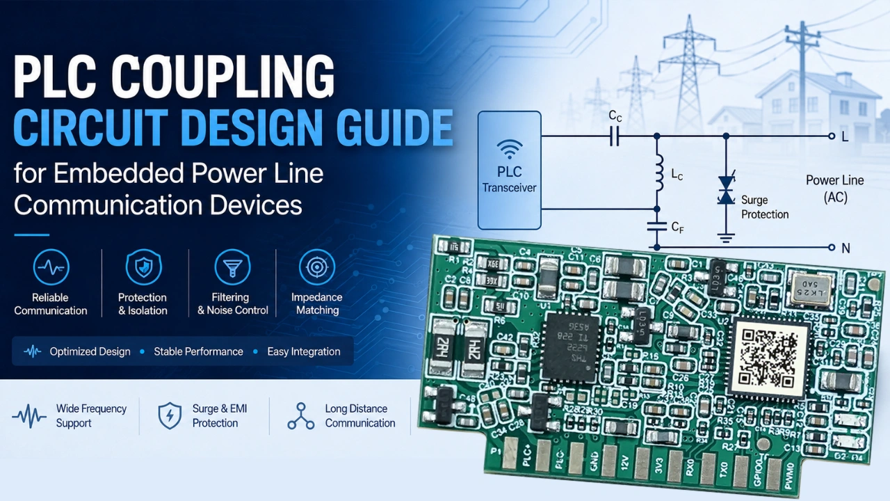
PLC Transceiver → Matching / Filtering → Coupling Network → Protection / Isolation → Power Line
Depending on the product architecture, some of these functions may be combined.
1. PLC Transceiver
The PLC transceiver generates and receives the communication signal.
In an embedded design, this may be implemented using:
- A PLC chipset
- A PLC modem
- A PLC communication module
- A system-on-chip PLC solution
- A customized PLC communication board
Using a pre-engineered PLC communication module can simplify the digital interface and communication software integration, while the external coupling architecture still needs to be designed for the target power network.
2. Signal Matching and Filtering
The PLC signal needs to be transferred efficiently between the transceiver and the power line.
Filtering and matching networks can help control:
- Passband characteristics
- Signal attenuation
- Impedance
- Harmonic content
- Out-of-band interference
- Receiver noise
The design should be based on the actual operating frequency range of the PLC system rather than using a generic filter.
3. Coupling Network
The coupling network transfers the PLC communication signal onto and from the power line.
Common coupling approaches include:
- Capacitive coupling
- Inductive coupling
- Transformer-based coupling
- Hybrid coupling architectures
The appropriate method depends on the application voltage, frequency range, isolation requirements, power-line topology, and regulatory requirements.
4. Protection
The power line is an electrically harsh environment.
PLC coupling circuits may encounter:
- Surge events
- Switching transients
- Lightning-induced disturbances
- Fast voltage changes
- Differential-mode noise
- Common-mode noise
- High-energy electrical disturbances
Protection components and isolation architecture should therefore be selected based on the actual installation environment and applicable safety requirements.
Protection should not be treated as an afterthought. It needs to be coordinated with the coupling network so that protection components do not excessively load or attenuate the PLC communication band.
PLC Coupling Circuit Design Principles
There is no universal PLC coupling circuit that works optimally for every application. The PLC coupling network should be designed according to the actual PHY frequency range and communication technology being used. For systems based on IEEE 1901.1, the standard defines PHY and MAC specifications for medium-frequency PLC applications
A practical design normally begins with the following parameters.
1. Define the PLC Frequency Band
The first step is to identify the communication frequency range.
The coupling circuit must provide an appropriate transfer path throughout the required PLC band. The selected PLC frequency band also affects the available communication bandwidth and the design requirements of the coupling network. See our PLC bandwidth calculation guide for more information.
For example, if the PLC communication system operates in a relatively high-frequency band compared with the AC power frequency, the coupling network must:
- Pass the PLC signal
- Suppress unwanted low-frequency energy
- Maintain acceptable insertion loss
- Avoid excessive phase distortion
- Provide predictable impedance
The coupling circuit should therefore be designed from the actual PLC PHY specifications rather than selected solely from nominal component values.
2. Understand the Power-Line Environment
The power line is not a controlled laboratory transmission line.
Its characteristics can vary significantly according to:
- Cable length
- Cable type
- Load type
- Number of connected devices
- Switching power supplies
- Motors
- LED drivers
- Inverters
- Transformers
- Electrical panels
- Building topology
- Phase configuration
A PLC network can therefore experience different impedance and noise conditions at different locations.
This is especially important for smart lighting and industrial PLC applications, where many loads may share the same electrical infrastructure.
3. Separate Communication and Power Functions
The coupling circuit must allow the PLC signal to coexist with the normal electrical power waveform.
Conceptually:
Power Line = Power-Frequency Energy + PLC Communication Signal + Electrical Noise
The coupling network extracts or injects the high-frequency communication component without interfering with the normal power-delivery function.
The communication path should therefore be designed so that the PLC signal sees an appropriate transmission path while the high-energy power-frequency component is controlled.
Capacitive vs. Inductive PLC Coupling
Two common approaches are capacitive and inductive coupling.
Capacitive Coupling
Capacitive coupling uses a capacitor or capacitor-based network to transfer high-frequency PLC signals.
Because capacitive impedance decreases as frequency increases, a capacitor can provide a path for higher-frequency communication signals while blocking DC and substantially restricting low-frequency power components.
Advantages can include:
- Compact implementation
- Relatively simple signal path
- Suitable for many embedded designs
- Potentially lower component count
However, the capacitor must be appropriately rated for the application, insulation system, transient environment, and applicable safety requirements.
The capacitor’s characteristics can also affect the PLC signal path, particularly at higher frequencies.
Inductive Coupling
Inductive coupling uses a magnetic component such as a coupling transformer or suitable inductor arrangement.
It can provide useful electrical isolation and controlled transfer characteristics depending on the architecture.
Potential advantages include:
- Galvanic isolation possibilities
- Controlled impedance transformation
- Good isolation between sections of the system
- Flexibility for certain industrial architectures
The design must account for:
- Core characteristics
- Winding structure
- Leakage inductance
- Parasitic capacitance
- Frequency response
- Saturation
- Insulation requirements
The coupling transformer is therefore not simply a “wireless” connection component. Its high-frequency characteristics directly influence PLC communication performance.
PLC Coupling Circuit and Electrical Isolation
Electrical isolation is one of the most important considerations when designing PLC equipment connected to hazardous-voltage power networks.
Depending on the product architecture, the PLC communication electronics may need to be isolated from the power line or other low-voltage circuitry.
Isolation considerations can include:
- Isolation voltage
- Creepage distance
- Clearance distance
- Insulation material
- Transformer construction
- Safety capacitor requirements
- PCB isolation slots
- Surge withstand capability
- Reinforced or basic insulation requirements
The required architecture depends on the end product and applicable standards.
For a commercial PLC product, engineers should not determine isolation solely from the nominal mains voltage. The complete electrical environment and required safety category must be considered.
PLC Coupling Circuit Impedance Matching
Impedance is another important factor in PLC communication performance.
A power line does not necessarily present a fixed impedance.
Instead, the effective impedance can change with:
- Frequency
- Cable length
- Connected loads
- Load switching state
- Electrical topology
- Number of PLC nodes
The coupling network therefore needs to provide an appropriate interface between the PLC transceiver and the variable power-line environment.
Poor matching can result in:
- Reduced transmitted signal level
- Increased reflection
- Reduced receiver signal-to-noise ratio
- Higher packet error rates
- Reduced communication range
For this reason, coupling-network optimization should ideally be performed using measurements rather than relying exclusively on theoretical calculations.
PLC Coupling Circuit Filtering
Filtering is commonly used to control the frequency response of the PLC interface.
A practical coupling network may include different filtering functions.
High-Pass Filtering
High-pass behavior can help separate the PLC communication band from the low-frequency power waveform.
Band-Pass Filtering
A band-pass network can help concentrate the coupling path around the intended PLC frequency range.
EMI Filtering
EMI filtering can reduce unwanted interference entering or leaving the PLC communication path.
However, filtering must be carefully coordinated with PLC communication requirements.
An aggressive EMI filter may reduce unwanted noise but can also attenuate the desired PLC signal.
Therefore:
EMI reduction and PLC signal transmission must be optimized together.
PLC Coupling Circuit Protection
Power-line-connected electronics require protection against abnormal electrical events.
Potential disturbances include:
- Surge voltage
- Fast transient bursts
- Electrostatic discharge
- Lightning-related disturbances
- Switching transients
- Overvoltage conditions
Protection may involve combinations of:
- Surge protection devices
- Voltage-limiting components
- Fuses or other current-limiting protection
- Filtering
- Isolation barriers
- Proper grounding architecture
The protection network must be coordinated with the coupling network.
A protection component with excessive parasitic capacitance, for example, can influence the PLC communication path.
Therefore, engineers should evaluate both:
Protection performance + PLC RF performance
rather than optimizing them independently.
PLC Coupling Circuit PCB Layout
A good schematic can still perform poorly if the PCB layout is not carefully designed.
For embedded PLC devices, PCB layout should consider both high-frequency signal integrity and electrical safety.
Keep the PLC Signal Path Short
The path between the PLC transceiver and coupling network should generally be kept as short and controlled as practical.
Long traces can introduce:
- Parasitic inductance
- Parasitic capacitance
- Unwanted radiation
- Additional signal loss
Separate Noisy Circuits
Switching power supplies, MOSFETs, relays, motor drivers, LED drivers, and other high-noise circuits can interfere with the PLC communication path.
Where possible, maintain appropriate physical separation between:
- PLC analog/RF circuitry
- Switching power supplies
- High-current traces
- Fast switching nodes
- Relay contacts
- Motor-control circuitry
Control Grounding
Grounding and return-current paths should be considered carefully.
A poorly controlled return path can allow switching noise to couple into sensitive PLC receiver circuitry.
Engineers should analyze:
- Signal return paths
- Power return paths
- Chassis connections
- Protective earth
- Digital ground
- Analog/RF ground
- Isolation boundaries
The correct architecture depends on the product’s electrical topology and safety requirements.
Common PLC Coupling Circuit Design Mistakes
Several design mistakes appear repeatedly in embedded PLC products. Power-line noise can significantly affect PLC communication performance. For a more detailed troubleshooting approach, see our PLC Signal Noise Troubleshooting Guide.
Mistake 1: Designing the Coupling Circuit Without Measuring the Power Line
The power-line impedance can vary substantially between applications.
A circuit optimized only through simulation may not perform equally well in an actual installation.
Better approach: validate the design using representative cable lengths, loads, and electrical environments.
Mistake 2: Adding Too Much Filtering
Additional filtering can reduce EMI but may also reduce the PLC signal.
The result can be a cleaner-looking spectrum but poorer communication performance.
Better approach: evaluate insertion loss and communication performance together.
Mistake 3: Ignoring Parasitic Components
At PLC operating frequencies, PCB traces, component packages, transformers, connectors, and protection devices all have parasitic characteristics.
These parasitics can change the actual circuit response.
Better approach: consider the complete physical implementation, not just the ideal schematic.
Mistake 4: Placing High-Noise Components Too Close to the PLC Circuit
Switching converters and LED drivers can generate significant broadband noise.
Better approach: separate high-noise switching sections from the PLC coupling and receiver circuitry.
Mistake 5: Treating Protection and Communication as Separate Designs
Protection components are directly connected to the power-line interface and can influence PLC performance.
Better approach: evaluate protection, filtering, isolation, and signal coupling as one integrated system.
Mistake 6: Using a Generic Coupling Circuit for Every PLC Application
A coupling network designed for one voltage, frequency range, cable topology, or application may not be suitable for another.
Better approach: optimize the coupling network according to the PLC PHY, power-line environment, safety requirements, and target application.
How to Test a PLC Coupling Circuit
A coupling circuit should be validated at both the component level and system level.
Important measurements can include:
1. Frequency Response
Measure the transfer characteristics across the intended PLC frequency range.
Important parameters include:
- Insertion loss
- Passband response
- Attenuation
- Resonance
- Phase response
2. Signal Level
Measure the PLC transmit signal at the power-line interface under representative operating conditions.
3. Receiver Sensitivity
Evaluate the minimum signal level at which reliable communication can be maintained.
4. Noise Performance
Measure the background noise across the PLC operating band.
Testing should include representative electrical loads rather than only a clean laboratory power source.
5. Communication Performance
Ultimately, the coupling circuit should be evaluated using actual communication metrics such as:
- Packet error rate
- Bit error rate
- Throughput
- Communication range
- Network stability
- Reconnection behavior
6. Environmental Testing
For industrial and outdoor applications, testing may also need to consider:
- Temperature
- Humidity
- Surge
- Electrical fast transients
- Electromagnetic interference
- Long cable runs
- Different load conditions
PLC Coupling Circuit Design for Smart Lighting
Smart lighting is a particularly useful application for PLC coupling circuits because the existing lighting power infrastructure can also provide the communication path. PLC coupling circuits are particularly important in PLC smart lighting systems because the same electrical infrastructure provides both power delivery and the communication path.
A typical PLC smart lighting node may contain:
AC Power → Power Supply → LED Driver / Lamp
and:
AC Power → PLC Coupling Circuit → PLC Module → MCU / Controller
This architecture allows the same electrical infrastructure to support both power delivery and communication.
A PLC smart lighting network can therefore support functions such as:
- Remote ON/OFF control
- Scheduled lighting
- Dimming
- Energy monitoring
- Fault detection
- Lamp status monitoring
- Group control
- Network management
- Gateway communication
For outdoor lighting, the coupling design also needs to account for long cable runs, switching power supplies, environmental transients, and variable electrical loads.
PLC Coupling Circuit Design for Embedded PLC Modules
When integrating a PLC communication module into an embedded product, the coupling network should be considered together with the host MCU, power supply, PCB, and power-line interface. For a practical hardware and firmware integration example, see our guide to integrating a PLC module into an embedded system.
Before designing the interface, engineers should identify:
- PLC operating frequency
- PLC modulation and PHY requirements
- Transmit output characteristics
- Receiver input requirements
- Required isolation
- Power-line voltage
- Power-line topology
- Expected cable length
- Typical electrical loads
- Surge and transient environment
- EMC requirements
- Applicable safety standards
This information determines the appropriate coupling architecture.
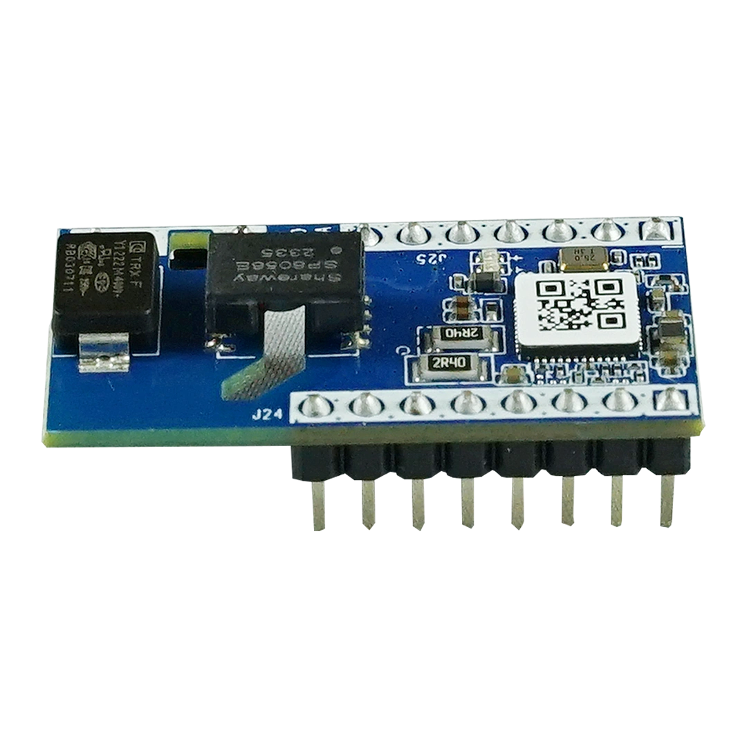
A PLC communication module can simplify the digital communication side of the product, but the power-line interface still requires careful hardware design. For OEM products using an embedded PLC communication module, the coupling interface should be designed according to the module’s electrical and PLC interface requirements. For example, the MN-L80C Power Line Communication Module provides a reference for module power supply and PLC signal coupling design.
Coupling Circuit vs. PLC Communication Module
It is useful to distinguish between the PLC module and the coupling circuit.
| Component | Main Function |
|---|---|
| PLC Chipset | Provides PLC processing and PHY/MAC functions |
| PLC Communication Module | Integrates PLC communication electronics into a reusable module |
| PLC Coupling Circuit | Connects the PLC communication signal to the power line |
| PLC Board | Complete PCB assembly containing the PLC and other circuits |
| PLC Gateway | Manages communication between PLC devices and an upper network |
In other words:
PLC module ≠ PLC coupling circuit
The PLC module handles the communication processing, while the coupling circuit provides the electrical interface to the power line.
For OEM embedded products, understanding this distinction helps engineers determine which parts should be integrated into the PLC module and which parts should remain on the customer’s main PCB.
Recommended PLC Coupling Circuit Design Workflow
A practical engineering workflow can be organized into eight steps.
Step 1 — Define the Application
Determine:
- Power-line voltage
- Frequency
- PLC frequency band
- Communication distance
- Environmental conditions
- Isolation requirements
Step 2 — Select the PLC Architecture
Choose the appropriate:
- PLC chipset
- PLC communication module
- Gateway architecture
- Host processor interface
Step 3 — Select the Coupling Topology
Evaluate capacitive, inductive, transformer-based, or other appropriate architectures.
Step 4 — Design Protection
Define the required transient and surge protection according to the target installation and safety requirements.
Step 5 — Design Filtering and Matching
Optimize the communication path for the target PLC frequency band and expected line impedance.
Step 6 — Design the PCB
Pay attention to:
- Signal routing
- Grounding
- Isolation
- Creepage
- Clearance
- Noise sources
- High-current paths
Step 7 — Laboratory Validation
Measure:
- Frequency response
- Signal level
- Noise
- Insertion loss
- Receiver performance
- Communication reliability
Step 8 — Field Validation
Test the embedded PLC device under realistic conditions with actual:
- Power cables
- Loads
- Switching equipment
- Lighting drivers
- Electrical panels
- Network distances
Field validation is especially important because the electrical characteristics of a real power network can differ significantly from laboratory conditions.
How to Improve PLC Coupling Circuit Reliability
A reliable PLC coupling design should not focus only on maximum signal strength.
The objective is to achieve a balanced design with:
Signal Quality + Protection + Isolation + EMC + Safety + Manufacturability
Several practical principles can help:
Use a validated PLC reference architecture
Starting from a proven PLC communication architecture can reduce development risk.
Characterize the actual power network
Measure representative loads and cable configurations.
Optimize the complete signal path
Evaluate the PLC module, coupling circuit, PCB, connector, cable, and power network together.
Test under worst-case conditions
Do not validate only under a clean and lightly loaded power line.
Consider production tolerances
Component tolerances, transformer variation, PCB manufacturing tolerances, and temperature can change the coupling response.
Validate EMC and communication simultaneously
A design that performs well from a communication perspective may still require additional EMC optimization.
PLC Coupling Circuit Design Checklist
Before finalizing an embedded PLC design, engineers can use the following checklist:
- PLC frequency range defined
- Power-line voltage identified
- Power-line topology identified
- Coupling topology selected
- Isolation requirements defined
- Surge protection defined
- EMI filtering evaluated
- PLC signal attenuation measured
- Impedance characteristics evaluated
- PCB creepage and clearance reviewed
- High-noise circuits physically separated
- PCB parasitics considered
- Frequency response measured
- Receiver sensitivity tested
- Communication reliability tested
- Real-world loads tested
- Temperature and environmental testing completed
- Applicable EMC and safety requirements reviewed