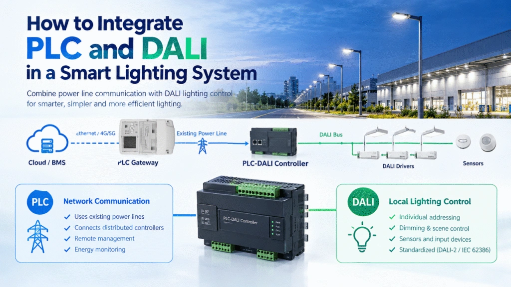
Power Line Communication (PLC) uses existing electrical power lines to transmit data. This eliminates the need for dedicated communication cables, making PLC an attractive solution for smart lighting, industrial automation, street lighting, energy management, and other IoT applications.
However, the same power line that carries electrical energy also carries the communication signal. Electrical equipment, switching devices, power supplies, motors, and other loads can introduce interference that reduces PLC communication quality.
When a PLC network experiences packet loss, unstable communication, slow networking, or intermittent device disconnections, signal noise should be one of the first factors to investigate.
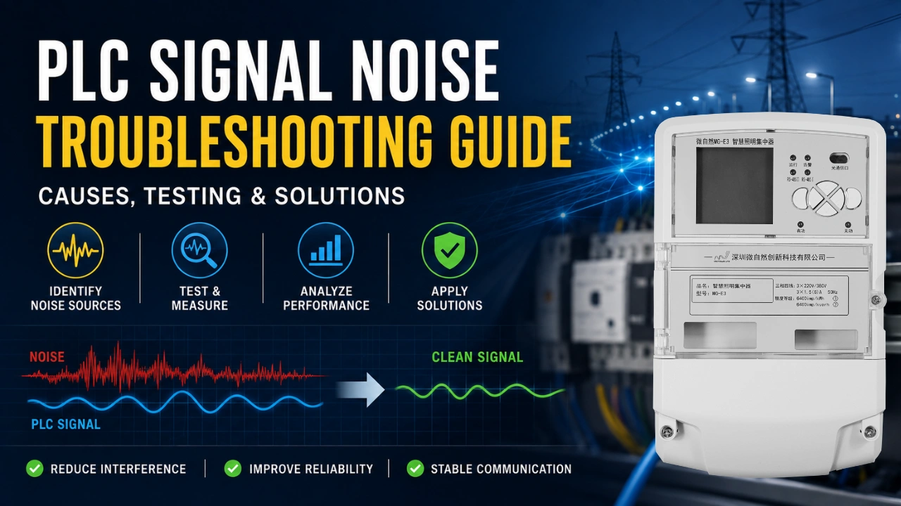
This PLC signal noise troubleshooting guide explains the main causes of PLC interference, how to identify noise problems, how to test a PLC network, and practical ways to improve communication reliability.
What Is PLC Signal Noise?
PLC signal noise is unwanted electrical interference that affects the communication signal transmitted over a power line.
A PLC modem injects a high-frequency communication signal onto the power line. At the same time, electrical equipment connected to the same line may generate unwanted high-frequency components.
When the noise level becomes significant compared with the PLC communication signal, the receiver may have difficulty correctly detecting and decoding the transmitted data.
In simple terms:
PLC communication quality depends on the relationship between the desired communication signal and the unwanted electrical noise.
A noisy power line can cause:
- Packet loss
- Communication retries
- Increased latency
- Unstable connections
- Slow network formation
- Failed device discovery
- Intermittent device disconnections
- Reduced communication distance
- Poor network throughput
- Unreliable remote control
For smart lighting systems, these problems may appear as lights that fail to respond, delayed commands, missing devices, or unstable communication between gateways and lighting controllers.
How PLC Signal Noise Affects Communication
A simplified PLC communication path looks like this:
PLC Transmitter → Power Line → Electrical Noise → PLC Receiver
The transmitter sends the PLC signal through the electrical network. Other equipment connected to the same network can introduce interference.
The receiver must distinguish the PLC signal from the background noise.
A useful engineering concept is the Signal-to-Noise Ratio (SNR):
SNR = Signal Power / Noise Power
A higher SNR generally provides better conditions for reliable communication.
If noise increases while the PLC signal remains unchanged, the effective SNR decreases. Depending on the PLC technology and implementation, this can result in more errors, retransmissions, reduced data rates, or loss of communication.
Therefore, PLC troubleshooting should not focus only on increasing transmitter power. It is often more effective to identify and reduce the source of interference.
Common Sources of PLC Signal Noise
PLC noise can come from many different electrical devices. The exact source depends on the application and electrical environment.
1. LED Drivers and Switching Power Supplies
LED drivers are common noise sources in modern lighting systems.
Many LED drivers use switching circuits that operate at high frequencies. Poor filtering or unsuitable power supply designs can introduce conducted electromagnetic interference into the power line.
In a PLC smart lighting system, this can be especially important because the lighting load and PLC communication system share the same electrical infrastructure.
Potential symptoms include:
- Communication becomes unstable when lights are switched on.
- PLC performance changes with different LED drivers.
- Communication is better when certain lighting circuits are disconnected.
- Specific groups of lamps cause communication problems.
Testing the network with individual lighting loads disconnected can help identify whether a particular driver is contributing to the problem.
2. Variable Frequency Drives and Motors
Industrial motors and variable frequency drives (VFDs) can generate significant electrical interference.
Typical sources include:
- Motor switching
- PWM drives
- Frequency converters
- Pumps
- Fans
- Compressors
- Industrial machinery
The interference may change depending on motor operating conditions.
For example, a PLC network may operate normally when a motor is stopped but become unstable when the motor starts or changes speed.
This makes time correlation an important troubleshooting method.
If PLC communication problems occur at the same time that a motor or VFD starts operating, investigate that equipment as a potential noise source.
3. Contactors, Relays, and Switching Equipment
Mechanical switching devices can generate transient disturbances when electrical loads are switched.
Examples include:
- Contactors
- Relays
- Circuit breakers
- Large lighting circuits
- Magnetic equipment
- Inductive loads
These disturbances may be particularly noticeable in systems where large loads are switched frequently.
4. Power Supplies and Chargers
Switch-mode power supplies can introduce high-frequency noise into electrical networks.
Potential sources include:
- Industrial power supplies
- Battery chargers
- EV charging equipment
- Computer power supplies
- UPS systems
- Inverters
In applications combining PLC communication with EV charging, photovoltaic systems, or energy storage systems, noise investigation should consider the complete electrical environment rather than only the PLC devices.
5. Solar Inverters and Power Electronics
PV inverters and other power electronic equipment can affect PLC communication because they use high-frequency switching circuits.
A useful troubleshooting approach is to compare PLC communication:
Before inverter operation → During inverter operation → After inverter operation
If communication quality changes significantly when the inverter starts or changes operating conditions, further investigation of conducted interference may be required.
Typical Symptoms of PLC Signal Noise
PLC signal noise does not always appear as a complete communication failure.
Different noise conditions can produce different symptoms.
| Symptom | Possible Cause |
|---|---|
| Devices cannot join the network | Excessive noise or weak signal |
| Communication is intermittent | Variable noise source |
| Packet loss increases | Low SNR or interference |
| Network formation is slow | Repeated communication retries |
| Commands are delayed | Retransmissions or congestion |
| Some lamps respond while others do not | Local electrical noise or attenuation |
| Communication fails when equipment starts | Switching transient or EMI |
| Communication distance is shorter than expected | Weak signal, attenuation, or noise |
| One branch works poorly | Local load or wiring problem |
| Gateway communicates with some devices but not others | Network topology, attenuation, or local interference |
These symptoms do not prove that noise is the cause. PLC communication problems can also result from attenuation, impedance changes, wiring topology, coupling problems, hardware issues, or configuration errors.
A systematic troubleshooting process is therefore important.
PLC Signal Noise Troubleshooting: Step-by-Step
Step 1: Confirm the Communication Problem
Before investigating noise, clearly define the problem.
Record:
- Which PLC devices are affected?
- When does the problem occur?
- Is the problem continuous or intermittent?
- How many devices are affected?
- Does the problem occur on one circuit or the entire network?
- Did the problem appear after adding new equipment?
- Does communication improve when specific loads are disconnected?
For example, if a street lighting system works correctly during the daytime but becomes unstable after the lighting fixtures turn on at night, the lighting loads should be investigated.
Step 2: Check PLC Network Topology
Noise is only one possible reason for poor PLC communication.
First check:
- Power line topology
- Cable length
- Distribution cabinets
- Branch circuits
- Phase connections
- Transformer boundaries
- Circuit breakers
- Coupling arrangements
- PLC gateway location
- Controller locations
A device that is electrically far away from the gateway may experience a weak communication signal even when the noise level is relatively low.
Therefore:
Weak PLC signal and high PLC noise are different problems and should be diagnosed separately.
Step 3: Identify When the Noise Appears
Intermittent noise is often easier to diagnose by correlating communication problems with electrical equipment.
Create a simple timeline:
| Event | PLC Communication |
|---|---|
| Motor OFF | Normal |
| Motor START | Communication unstable |
| Motor RUNNING | Packet loss |
| Motor STOP | Communication recovers |
If PLC performance consistently changes with a specific electrical load, that load becomes a strong candidate for further testing.
This method is particularly useful in factories, warehouses, pump stations, tunnels, ports, and other industrial environments.
Step 4: Disconnect Suspected Loads
One of the simplest diagnostic methods is controlled load isolation.
Temporarily disconnect or switch off suspected equipment and observe whether PLC communication improves.
Potential test targets include:
- LED drivers
- VFDs
- Motors
- Inverters
- Power supplies
- Chargers
- UPS systems
- Industrial equipment
If communication improves significantly after a specific load is disconnected, investigate that equipment and its connection to the power network.
Important: Electrical isolation and testing should be performed by qualified personnel using appropriate safety procedures.
Step 5: Measure the PLC Signal and Noise
For engineering-level troubleshooting, measurement is more reliable than relying only on communication status.
Depending on the PLC technology and system design, engineers may evaluate:
- PLC signal level
- Noise level
- SNR
- Frequency spectrum
- Packet error rate
- Retransmission rate
- Communication throughput
- Link quality
- Received signal strength
An oscilloscope or spectrum-analysis equipment can help identify unwanted electrical activity, while PLC diagnostic tools can provide communication-level information.
The objective is to answer two questions:
Is the PLC signal too weak?
and
Is the electrical noise too high?
These questions lead to different solutions.
Step 6: Check the Frequency Range
Different PLC technologies operate over different frequency ranges.
Noise is particularly important when its frequency components overlap with or interfere with the PLC communication band.
For example, a switching power supply may generate harmonics or broadband conducted noise that affects part of the PLC operating spectrum.
A frequency-domain measurement can therefore provide more useful information than simply measuring voltage with a standard multimeter.
The troubleshooting process should identify:
- PLC operating frequency range
- Dominant noise frequencies
- Noise amplitude
- Noise behavior under different loads
- Whether the noise overlaps the PLC communication band
Step 7: Test the Network With Different Loads
If the system contains many lighting fixtures or electrical devices, test the network under different load combinations.
For example:
Test A: PLC communication with all loads OFF
Test B: PLC communication with lighting ON
Test C: PLC communication with industrial equipment ON
Test D: PLC communication with suspected noise source isolated
Comparing the results can help determine whether the communication problem is load-dependent.
This is particularly useful for PLC smart lighting networks because a large number of LED drivers may be connected to the same power infrastructure.
Step 8: Check for Electrical Noise Filters
If a specific device is confirmed as a noise source, an appropriate EMI filter or noise suppression solution may be considered.
The filter must be selected carefully.
A filter designed to suppress unwanted high-frequency components can also attenuate the PLC communication signal if it affects the same frequency range.
Therefore:
Do not select a filter simply because it reduces electrical noise. Verify that it does not significantly reduce the PLC communication signal.
This is one of the most important considerations when applying EMI filters to PLC systems.
Step 9: Check PLC Coupling and Isolation
PLC communication performance can also be affected by how the communication signal travels through the electrical network.
Investigate:
- Coupling between circuits
- Phase configuration
- Distribution equipment
- Isolation devices
- Transformers
- Filters
- Long cable sections
- Branch circuits
A PLC signal may be present at the transmitter but significantly attenuated before reaching the receiver.
In this situation, increasing the signal alone may not solve the problem. The electrical path itself needs to be investigated.
Step 10: Retest After Each Change
Avoid making multiple changes simultaneously.
A better troubleshooting process is:
Measure → Change One Variable → Measure Again
For example:
- Record the original PLC communication performance.
- Disconnect one suspected noise source.
- Test the PLC network again.
- Compare the results.
- Reconnect the device.
- Test another suspected source.
This creates a repeatable troubleshooting process and makes it easier to identify the actual cause.
Practical PLC Noise Troubleshooting Example
Consider a smart street lighting system with a PLC gateway and multiple PLC lighting controllers.
The system works correctly during the daytime but several lighting controllers become intermittently unreachable after sunset.
A practical troubleshooting process could be:
1. Check the timing
The problem appears when the street lights turn ON.
2. Check communication performance
Record device availability, packet loss, and link quality before and after the lights turn on.
3. Isolate lighting groups
Turn on different groups of lamps separately.
4. Identify the problematic branch
One lighting branch causes a significant deterioration in communication performance.
5. Test individual fixtures
Disconnect individual fixtures or drivers from the branch.
6. Identify the noise source
One LED driver produces significantly more interference than the other fixtures.
7. Evaluate the solution
Possible solutions may include:
- Replacing the problematic driver
- Improving the driver’s EMI filtering
- Adding a suitable filter
- Improving PLC signal coupling
- Modifying the electrical topology
8. Verify the complete network
After the corrective action, test the entire PLC network again under normal operating conditions.
This approach is more reliable than simply replacing the PLC gateway.
PLC Signal Noise vs. Weak Signal
One of the most common troubleshooting mistakes is treating every PLC communication problem as noise.
There are at least two different scenarios.
Scenario 1: Weak PLC Signal
The communication signal reaching the receiver is too weak.
Possible causes include:
- Long cable distance
- High line attenuation
- Poor coupling
- Electrical isolation
- Complex distribution topology
- Impedance problems
Scenario 2: High Noise
The PLC signal may be strong enough, but unwanted electrical interference makes reliable decoding difficult.
Possible causes include:
- Switching power supplies
- LED drivers
- Motors
- VFDs
- Inverters
- Chargers
- Industrial equipment
Scenario 3: Weak Signal + High Noise
This is often the most difficult condition.
If the PLC signal is weak and the electrical environment is noisy, communication performance can deteriorate rapidly.
Therefore, effective troubleshooting should evaluate both signal strength and noise level.
How to Reduce PLC Signal Noise
Once the source of interference has been identified, several strategies can be considered.
1. Use Low-Noise Electrical Equipment
Select power supplies, LED drivers, and other equipment with appropriate electromagnetic compatibility performance.
For smart lighting projects, the LED driver is particularly important because large numbers of drivers may share the same power network.
2. Improve EMI Filtering
Appropriate EMI filtering can reduce conducted interference.
However, the filter must be compatible with the PLC communication frequency range.
An incorrectly selected filter can reduce both:
- unwanted noise, and
- the desired PLC signal.
Therefore, filter performance should be evaluated together with PLC communication performance.
3. Isolate Strong Noise Sources
Where practical, high-noise equipment can be electrically separated from sensitive PLC communication sections.
For example, industrial machinery, VFDs, or other power electronics may require different circuit arrangements depending on the project architecture.
4. Improve Power Network Design
A well-designed electrical network can improve PLC reliability. If you are a new user, can first see this article PLC Network Design Guide for Smart Lighting Systems.
Consider:
- Circuit segmentation
- PLC gateway placement
- Branch length
- Electrical topology
- Coupling
- Noise-source location
- Load distribution
PLC network design should consider communication requirements from the beginning rather than treating signal quality as an afterthought.
5. Select a PLC Technology Suitable for the Environment
Different PLC technologies use different modulation methods, frequency ranges, coding techniques, and communication mechanisms.
For example, PLC systems may use technologies such as:
- FSK
- OFDM
- Narrowband PLC
- Broadband PLC
The most suitable solution depends on:
- Communication distance
- Data requirements
- Electrical environment
- Noise characteristics
- Network topology
- Application requirements
In harsh industrial or municipal environments, selecting a PLC solution designed for the actual electrical environment can be more effective than attempting to solve every problem with external filtering.
PLC Noise Troubleshooting Checklist
Use the following checklist when investigating unstable PLC communication.
Electrical Environment
- Identify all major electrical loads.
- Check LED drivers and switching power supplies.
- Check motors and VFDs.
- Check solar inverters and chargers.
- Check contactors and relays.
- Identify recently installed equipment.
PLC Network
- Check gateway location.
- Check cable distance.
- Check branch circuits.
- Check phase configuration.
- Check coupling and isolation.
- Check network topology.
Measurement
- Record PLC communication performance.
- Measure signal level if supported.
- Measure noise level if equipment is available.
- Check SNR or link-quality indicators.
- Check packet loss.
- Check retransmission behavior.
- Compare communication before and after suspected loads operate.
Troubleshooting
- Isolate suspected noise sources.
- Test one load at a time.
- Evaluate EMI filtering.
- Retest after each modification.
- Verify the complete network under normal operating conditions.