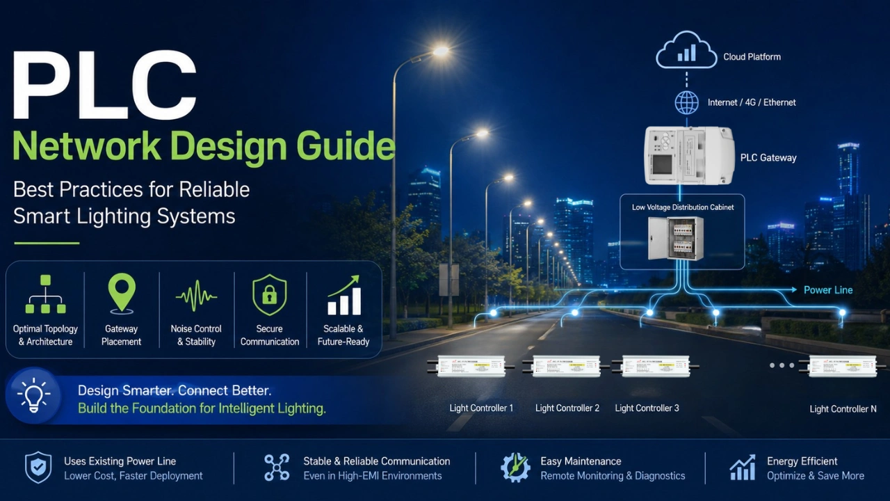
As cities, factories, warehouses, and campuses continue adopting smart lighting, Power Line Communication (PLC) has become one of the most reliable communication technologies available. Unlike wireless systems that depend on radio signals, PLC transmits data through existing electrical power lines, reducing installation costs while providing stable communication in environments where wireless technologies struggle.
However, achieving excellent communication performance depends heavily on proper network design. Poor electrical planning, incorrect gateway placement, or excessive electrical noise can reduce network stability and increase maintenance costs.
This PLC Network Design Guide explains the principles, best practices, and engineering considerations for designing a reliable PLC smart lighting network. If you’re new to PLC technology, first read our How PLC Lighting Works guide to understand the communication principles before designing a network.
Why PLC Network Design Matters
Even though PLC uses existing power cables, it should not be considered a “plug-and-play” solution for every installation.
A well-designed PLC network provides: Proper network planning is also one of the key factors affecting long-term operating costs. You can learn more in our PLC vs Wireless Lighting Cost Comparison article.
- Stable two-way communication
- Fast device discovery
- Low packet loss
- High network availability
- Reduced maintenance costs
- Easier future expansion
Poor network planning can result in:
- Communication failures
- Slow response times
- Signal attenuation
- Frequent offline devices
- Difficult troubleshooting
Proper network design ensures that every lighting controller can reliably communicate with the central management platform.
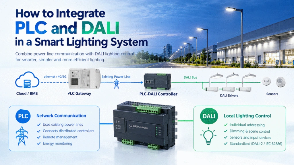
How a PLC Smart Lighting Network Works
A typical PLC lighting network consists of several layers.
Cloud Platform
        │
Internet / 4G / Ethernet
        │
PLC Gateway (Concentrator)
        │
Low Voltage Distribution Cabinet
        │
Power Line
 ├── Light Controller 1
 ├── Light Controller 2
 ├── Light Controller 3
 ├── ...
 └── Light Controller N
To better understand each communication layer, see our PLC Smart Lighting Topology Explained article.
The gateway injects communication signals into the power line, while each lighting controller receives commands and returns operating data through the same electrical cable supplying power.
No additional communication wiring is required.
PLC Network Topologies
Several network architectures are commonly used depending on the application.
1. Star Topology
Most common for street lighting.
Gateway
   │
Distribution Cabinet
├── Circuit A
├── Circuit B
├── Circuit C
Different projects may require different network structures. For example, PLC Street Lighting Solutions and PLC Tunnel Lighting Solutions use different topology designs depending on the electrical distribution network.
Advantages:
- Easy maintenance
- Simple fault isolation
- Good scalability
Suitable for:
- Municipal street lighting
- Parking lots
- Industrial parks
2. Tree Topology
Frequently used in campuses and industrial facilities.
Gateway
   │
Main Panel
   │
Sub Panel
   │
Lighting Branches
Advantages:
- Supports large installations
- Efficient cable utilization
- Easy expansion
3. Mesh-Assisted PLC
Modern PLC systems allow neighboring devices to relay communication if direct communication becomes difficult.
Benefits include:
- Improved reliability
- Alternative communication paths
- Better coverage
- Increased network resilience
Planning Gateway Placement
Gateway placement is one of the most important design decisions.
General recommendations include:
- Install gateways inside electrical distribution cabinets.
- Avoid placing gateways behind isolation transformers unless specifically supported.
- Ensure stable Ethernet or cellular backhaul.
- Provide adequate ventilation.
- Protect gateways from moisture and excessive heat.
For large projects, use multiple gateways instead of one oversized network.
Network Segmentation
Rather than connecting hundreds of devices to a single gateway, divide the network into logical sections.
Example:
| Area | Devices | Gateway |
|---|---|---|
| Parking Area | 80 | Gateway 1 |
| Main Road | 120 | Gateway 2 |
| Warehouse | 60 | Gateway 3 |
| Office Area | 40 | Gateway 4 |
Benefits include:
- Lower communication latency
- Better reliability
- Easier maintenance
- Faster troubleshooting
Consider Electrical Distribution
PLC communication quality depends on the electrical infrastructure.
Important considerations include:
Phase Distribution
Three-phase systems should be evaluated carefully.
Communication between phases may require:
- Phase couplers
- Proper transformer design
- Compatible PLC equipment
Transformer Boundaries
PLC signals usually cannot cross distribution transformers without additional equipment.
Each transformer generally requires its own PLC network.
Circuit Breakers
Most circuit breakers have minimal impact on PLC signals.
However:
- Surge protectors
- EMI filters
- Isolation transformers
may attenuate communication signals.
These devices should be evaluated during network design.
Minimize Electrical Noise
Electrical noise is the most common cause of PLC communication degradation.
Typical noise sources include:
- Variable Frequency Drives (VFD)
- Welding machines
- Industrial motors
- Switching power supplies
- Elevator systems
- HVAC equipment
Possible mitigation methods:
- Install signal couplers
- Use PLC filters where necessary
- Separate noisy industrial loads
- Improve grounding
- Optimize cable routing
Communication Distance
Communication distance depends on several factors:
- Cable quality
- Cable length
- Electrical noise
- Number of branches
- Network loading
Typical smart lighting projects achieve stable communication across extensive low-voltage lighting circuits when gateways are properly positioned and the electrical network is well designed. Actual coverage varies by site conditions and should be validated during commissioning.
Device Address Planning
Every controller should have a logical address.
Example:
| Device | Address |
|---|---|
| Pole 001 | 001 |
| Pole 002 | 002 |
| Pole 003 | 003 |
| Pole 004 | 004 |
Logical numbering simplifies:
- Maintenance
- GIS mapping
- Fault diagnosis
- Asset management
Commissioning Best Practices
Before handing over the project:
- Verify every controller is online.
- Measure communication success rate.
- Test remote switching.
- Test dimming.
- Confirm alarm reporting.
- Simulate communication recovery.
- Validate firmware versions.
- Record network topology.
Security Considerations
Modern PLC systems should include:
- Device authentication
- Encrypted communication
- User access control
- Secure cloud connectivity
- Firmware verification
- Remote update management
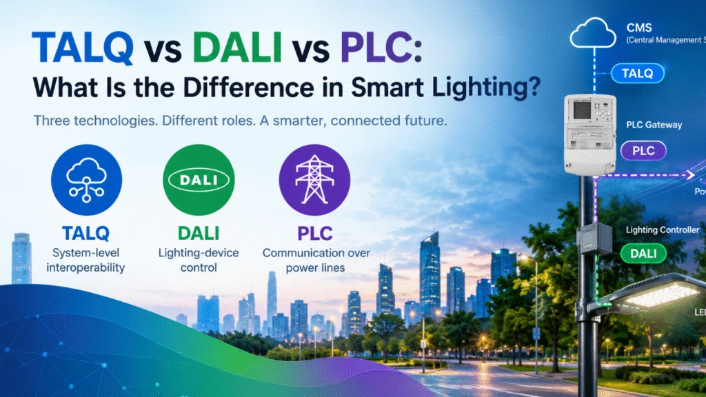
Cybersecurity becomes increasingly important as smart lighting integrates with broader Smart City platforms. Modern smart lighting systems increasingly support standardized interfaces such as TALQ.
Designing for Future Expansion
A well-designed PLC network should accommodate future growth.
Plan for:
- Additional lighting circuits
- Environmental sensors
- Energy meters
- EV charging integration
- Solar lighting systems
- AI-powered vision sensors
- Traffic monitoring devices
Choosing scalable hardware and modular network architecture reduces future upgrade costs.
Common Design Mistakes
Avoid these common issues:
- Installing too many devices on one gateway
- Ignoring electrical noise sources
- Poor grounding
- No network segmentation
- Incorrect gateway placement
- Failing to document device addresses
- Overlooking transformer boundaries
- Skipping communication testing
Proper engineering during the design phase can prevent costly maintenance later.
PLC Network Design Checklist
Before deployment, confirm:
- ✓ Electrical drawings reviewed
- ✓ Gateway locations selected
- ✓ Transformer boundaries identified
- ✓ Communication distances evaluated
- ✓ Electrical noise sources assessed
- ✓ Device addressing completed
- ✓ Network segmentation planned
- ✓ Security configured
- ✓ Remote monitoring verified
- ✓ Future expansion considered
Why Choose MicroNature PLC Smart Lighting Solutions?
MicroNature develops complete PLC-based smart lighting solutions for municipal, industrial, and commercial applications. Our portfolio includes PLC communication modules, gateways, single-light controllers, dimmable drivers, sensors, and cloud management software designed to simplify deployment and improve long-term reliability.
Key advantages include:
- Uses existing power lines—no additional communication cabling
- Fast automatic networking and remote commissioning
- Reliable communication in high-EMI environments
- Cloud-based monitoring, scheduling, alarms, and energy analytics
- Open APIs for integration with third-party smart city platforms
- Flexible deployment with Ethernet, fiber, or 4G/5G backhaul
Whether you’re planning a new smart lighting project or upgrading legacy infrastructure, a well-designed PLC network provides a scalable foundation for intelligent lighting control.