OEM products increasingly need reliable communication without adding complex communication wiring. For industrial controllers, smart lighting, meters, emergency lighting, EV charging equipment, and other electrical products, Power Line Communication (PLC) can provide a practical way to transmit data over existing power lines.
However, integrating a PLC function into an OEM product is more than simply adding a PLC chip or module to a PCB. The module must match the host product’s power supply, communication interface, PCB architecture, firmware, mechanical structure, and operating environment.
This OEM PLC Module Customization Guide explains the major engineering decisions involved in developing a customized PLC communication module for an OEM product.
What Is OEM PLC Module Customization?
OEM PLC module customization means adapting a PLC communication module to meet the electrical, communication, mechanical, firmware, and application requirements of a specific OEM product.
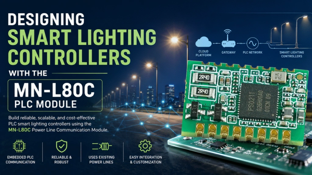
Instead of developing the entire PLC communication circuit from scratch, an OEM customer can integrate a customized PLC module into its existing hardware.
A customized module may include:
- PLC communication PHY
- MCU or processor
- Line driver
- Power supply circuit
- UART, SPI, GPIO, PWM, ADC, or other interfaces
- Communication protocol
- Firmware
- Network configuration
- Protection circuits
- EMC/EMI design
- Customized PCB dimensions
- Connectors and pin definitions
For example, a lighting manufacturer may integrate a PLC module into a lighting controller so that the controller can communicate with a central gateway through the existing power line.
The same concept can be applied to other electrical products.
Why Customize a PLC Module for an OEM Product?
A standard PLC module is often sufficient for evaluation or proof-of-concept development. Before you start, please first see our article How to Add PLC Communication to Existing Electrical Products. However, production products may have requirements that a standard module cannot satisfy. For PLC standard can see IEEE for reference.
Common OEM customization requirements include:
1. Different communication interfaces
The host controller may use:
- UART
- SPI
- I²C
- GPIO
- PWM
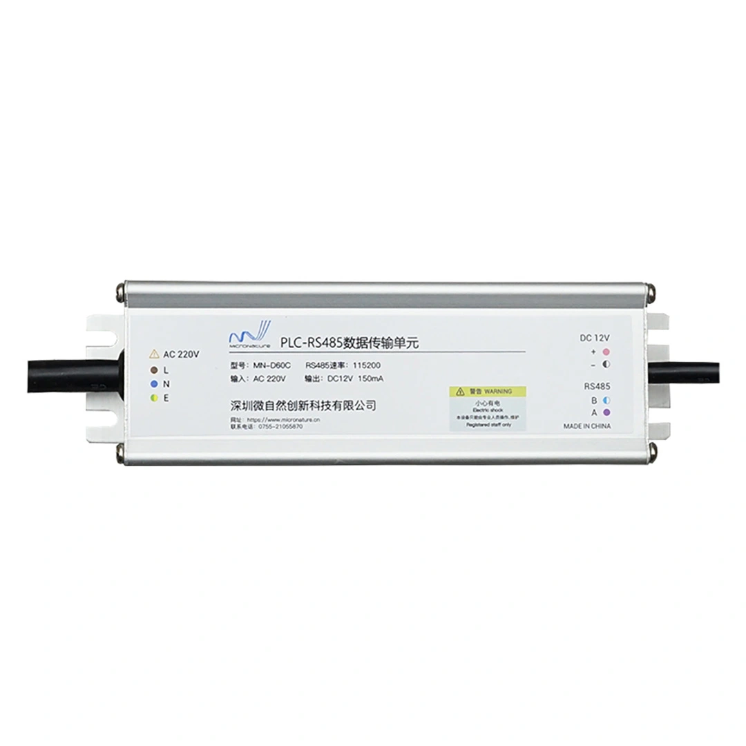
- RS-485
- Analog interfaces
The PLC module needs to provide a compatible interface and electrical level.
2. Different power supply
The OEM product may provide:
- 3.3 V
- 5 V
- 12 V
- 24 V
- AC power
- DC power
The PLC module’s power architecture must be designed accordingly.
3. Mechanical constraints
The module may need to fit inside:
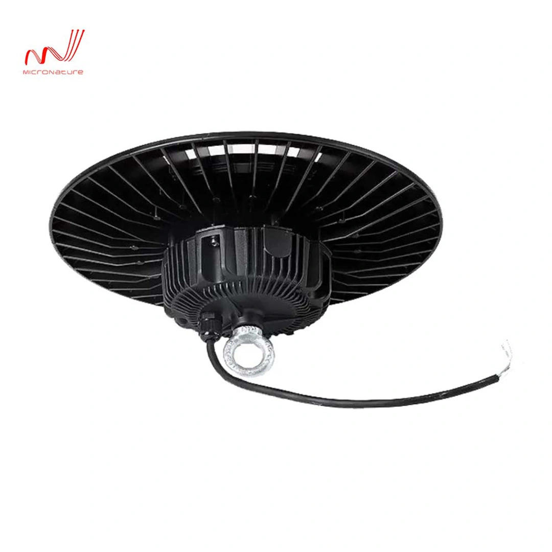
- Lighting drivers
- Controllers
- Meter enclosures
- Electrical cabinets
- Emergency lighting equipment
- EV charging equipment
- Industrial control equipment
Therefore, module dimensions, mounting holes, connector positions, and component height can become important customization parameters.
4. Customized communication protocols
The OEM product may need the PLC module to communicate with an existing MCU using a specific protocol or command structure.
5. Application-specific firmware
The PLC module may need custom functions for:
- Device addressing
- Network joining
- Data transmission
- Device discovery
- Parameter configuration
- Diagnostics
- OTA updates
- Error reporting
Key Parameters to Define Before Customizing a PLC Module
Before starting an OEM PLC module project, the customer should prepare a clear technical specification. PLC Module Design Checklist for OEM Development | Hardware & Testing this article is helpful to check.
A useful specification can be divided into eight areas:
| Category | Key Questions |
|---|---|
| PLC communication | Which PLC standard, frequency band, data rate and topology? |
| Host interface | UART, SPI, GPIO, PWM, etc.? |
| Power supply | What voltage and current are available? |
| PCB | What are the dimensions and mounting requirements? |
| Firmware | Which functions and protocols are required? |
| Environment | Temperature, humidity, EMC and installation conditions? |
| Mechanical | Connector, enclosure and component-height restrictions? |
| Production | Prototype quantity, certification and expected annual volume? |
Defining these requirements early can significantly reduce redesign during development.
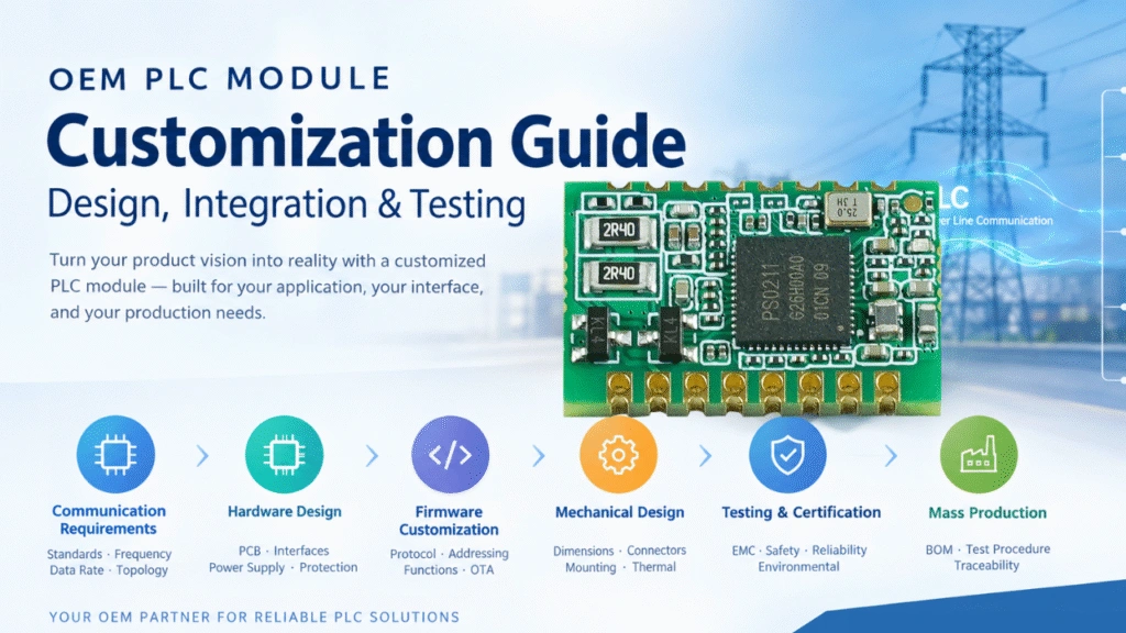
1. Define the PLC Communication Requirements
The first step is determining how the OEM device will communicate over the power line.
Important parameters include:
PLC frequency
Different PLC technologies operate at different frequency ranges.
The selected frequency should consider:
- Power-line characteristics
- Regulatory requirements
- Noise environment
- Communication distance
- Target application
- Existing PLC devices
Data rate
The required data rate depends on the application.
For smart lighting, for example, the system may only need relatively small packets containing:
- ON/OFF commands
- Dimming levels
- Voltage
- Current
- Power
- Energy
- Fault status
- Sensor information
An industrial IoT application may require a different communication architecture.
Network topology
The OEM system should define whether it uses:
- Point-to-point communication
- Star topology
- Tree topology
- Mesh networking
- Hybrid architecture
For large PLC lighting networks, the network architecture should also consider gateway capacity, device addressing, network discovery, and communication reliability.
2. Select the PLC Chipset or Module Architecture
There are generally two approaches to OEM PLC development. If you are a new user, can first see this article PLC Module vs PLC Chipset vs PLC Board: What’s the Difference? for reference.
Option A: Integrate a PLC chipset
The OEM develops the PLC circuit directly around a PLC chipset.
This provides greater control over:
- PCB architecture
- Component selection
- RF/analog design
- Firmware
- Power supply
- Production cost
However, it requires more engineering resources and PLC development experience.
Option B: Integrate an embedded PLC module
The OEM integrates a pre-developed PLC communication module into its product.
This can simplify:
- Hardware development
- PLC circuit design
- Firmware integration
- Prototype development
- Testing
- Production
For companies that already have an MCU-based product but do not want to redesign the complete PLC communication circuit, a customized embedded PLC module can be a practical approach.
3. Define the Host MCU Interface
One of the most important decisions is how the PLC module communicates with the OEM product’s main controller.
Common interfaces include:
UART
UART is widely used for embedded PLC integration because it is simple and requires relatively few pins.
Typical architecture:
Host MCU ↔ UART ↔ PLC Module ↔ Power Line
The host MCU can send commands to the PLC module while the module handles PLC communication.
SPI
SPI can be useful when higher-speed communication between the host MCU and PLC module is required.
GPIO
GPIO pins can be used for:
- Reset
- Interrupt
- Status
- Network state
- Fault indication
PWM
PWM may be useful in products where the PLC module needs to interact with lighting or motor-control functions.
The interface should be defined before PCB development because the pin assignment and electrical design can affect the entire module layout.
4. Match the PLC Module Power Supply
Power compatibility is another critical consideration.
The OEM customer should provide:
- Input voltage
- Voltage tolerance
- Maximum current
- Startup conditions
- Available DC rails
- Power sequencing requirements
For example, if the host product already provides a stable 3.3 V rail, the PLC module may be designed around that supply.
If the product only provides a higher-voltage DC rail, the module may require an additional DC/DC or LDO stage.
For products connected directly to AC mains, the isolation and protection architecture must also be carefully evaluated.
Do not assume that an existing PLC module can simply be connected to any available voltage.
The module power architecture must be designed according to the actual host product.
5. Customize the PLC Line Interface
The PLC line interface is one of the most application-sensitive sections of the design.
It typically includes the PLC transceiver, line driver, coupling network, filtering, and protection components.
The design should consider:
- AC/DC line voltage
- Line impedance
- Noise
- Surge
- EMI
- ESD
- Lightning environment
- Isolation requirements
- Communication distance
For industrial and outdoor applications, the electrical environment can be significantly noisier than a laboratory test environment.
Therefore, PLC communication should be tested using the actual target power network whenever possible.
6. Design the PCB for the OEM Product
A customized PLC module should fit the host product mechanically and electrically.
Typical PCB customization requirements include:
- PCB length
- PCB width
- PCB thickness
- Mounting holes
- Connector position
- Pin spacing
- Component height
- Keep-out areas
- Shielding requirements
- Heat dissipation
- Installation direction
For example, a PLC module installed inside a lighting driver may have strict height restrictions.
A module installed inside an electrical cabinet may have significantly more available space.
Therefore, the mechanical environment should be considered at the beginning of the design rather than after the circuit has been completed.
7. Customize the Pin Definition
OEM customers may have different requirements for the module connector.
A customized pinout may include:
| Pin | Function |
|---|---|
| VCC | Module power |
| GND | Ground |
| TX | UART transmit |
| RX | UART receive |
| RESET | Hardware reset |
| INT | Interrupt |
| GPIO | Configurable I/O |
| PWM | PWM interface |
| ADC | Analog input |
| SPI | SPI interface |
The actual pin assignment should be determined according to the host MCU and PCB architecture.
A good pinout should also consider future product revisions.
Leaving several configurable GPIOs can provide useful flexibility for future versions.
8. Customize the PLC Firmware
Hardware is only one part of an OEM PLC project.
Firmware customization may be equally important.
Typical firmware functions include:
Device addressing
Each PLC device may require a unique logical address.
Network discovery
The module can participate in network discovery or automatic network configuration.
Data transmission
The firmware defines how application data is packaged and transmitted through PLC.
Error handling
The module can provide information about:
- Communication failure
- CRC errors
- Timeout
- Network disconnection
- Invalid commands
Configuration
OEM products may require configurable parameters such as:
- Device ID
- Baud rate
- Communication parameters
- Network address
- Retry count
- Transmission interval
OTA or remote updates
For large-scale deployments, firmware update capability can reduce maintenance costs.
The exact firmware architecture should be agreed upon before mass production.
9. Define the Communication Protocol Between the Host MCU and PLC Module
A customized PLC module should have a clearly defined host communication protocol.
For example:
Host MCU → PLC Module
Command | Address | Data Length | Data | CRCThe PLC module processes the command and transmits the corresponding data over the power line.
The remote PLC module can then send the received information to its host MCU.
A protocol specification should define:
- Command format
- Data format
- Addressing
- CRC
- Timeout
- Retry mechanism
- Error codes
- Maximum packet size
- Version compatibility
This makes hardware and firmware integration much easier.
10. Consider EMC and Noise From the Beginning
PLC communication intentionally uses the power line as a communication medium.
Unfortunately, the same power line may also contain electrical noise.
Potential noise sources include:
- LED drivers
- Switching power supplies
- Motors
- Inverters
- Variable-frequency drives
- EV chargers
- Industrial equipment
- Relays
- Contactors
Therefore, PLC module design should consider EMC and noise immunity from the beginning.
Potential design measures include:
- Filtering
- Proper grounding
- PCB layout optimization
- Surge protection
- ESD protection
- Line coupling optimization
- Isolation
- EMI testing
A module that works well on a laboratory bench may behave differently when connected to a real industrial power network.
11. Prototype Testing
Before mass production, the customized PLC module should go through several stages of testing. How to Test a PLC Module Before Mass Production this article may lead you a correct test guide.
Hardware testing
Verify:
- Supply voltage
- Current consumption
- Interface levels
- Reset behavior
- GPIO functions
- Thermal behavior
PLC communication testing
Measure:
- Communication distance
- Packet success rate
- Data rate
- Network discovery
- Retry behavior
- Multi-device communication
Noise testing
Test communication under different electrical loads.
For example:
- LED drivers ON/OFF
- Motors operating
- Switching power supplies
- Different cable lengths
- Different load conditions
Environmental testing
Depending on the application:
- High temperature
- Low temperature
- Humidity
- Vibration
- Surge
- ESD
- EMC
12. Test the Module Inside the Final OEM Product
This step is often overlooked.
Testing the PLC module by itself is not enough.
The final product should be tested as a complete system:
PLC Module + Host MCU + Power Supply + Electrical Load + Power Network
For a smart lighting product, for example:
Cloud → Gateway → Power Line → PLC Controller → Lighting Driver → LED Luminaire
Testing the complete system helps identify problems caused by the interaction between the PLC module and other components.
13. Certification and Regulatory Requirements
The required certifications depend on the target market and product category.
An OEM PLC project may need to consider requirements related to:
- EMC
- Electrical safety
- Radio or conducted emissions
- Surge immunity
- ESD
- Environmental compliance
- Product-specific regulations
Certification requirements should be identified at the beginning of the project.
Changing the PCB or communication architecture late in development can increase certification costs and delay production.
14. Prepare for Mass Production
Once the prototype is validated, the module design should be prepared for production.
Important items include:
BOM
Define:
- Components
- Approved alternatives
- Lifecycle status
- Supplier information
Gerber files
The PCB manufacturing files should be released according to the final revision.
Firmware
The production firmware version should be controlled and documented.
Test procedure
Production testing may include:
- Power-on test
- Interface test
- PLC communication test
- Functional test
- Programming
- Calibration
Traceability
For large OEM projects, production traceability can help identify:
- Hardware revision
- Firmware version
- Production batch
- Serial number
OEM PLC Module Customization Process
A typical OEM project can follow this workflow:
Step 1 — Requirement Analysis
Define the application, PLC network, interface, power supply, mechanical requirements, and target market.
↓
Step 2 — Technical Proposal
Select the appropriate PLC architecture and define the hardware/software customization scope.
↓
Step 3 — Hardware Design
Customize the PCB, power supply, line interface, connectors, and host interface.
↓
Step 4 — Firmware Development
Implement the host protocol, PLC communication, device management, and application functions.
↓
Step 5 — Prototype
Build engineering samples and integrate them into the OEM product.
↓
Step 6 — System Testing
Test PLC communication under real electrical loads and network conditions.
↓
Step 7 — Certification
Complete applicable EMC, safety, and product certification.
↓
Step 8 — Pilot Production
Run a small production batch to validate manufacturing and testing procedures.
↓
Step 9 — Mass Production
Release the final hardware, firmware, BOM, production test procedure, and quality specifications.
How to Choose an OEM PLC Module Development Partner
When evaluating a PLC module supplier, don’t look only at the module datasheet.
Ask whether the supplier can support the complete development process.
Important questions include:
Hardware
- Can the PCB be customized?
- Can the power supply be customized?
- Can the connector and pinout be changed?
- Can the module dimensions be customized?
Firmware
- Can the host communication protocol be customized?
- Can firmware functions be modified?
- Is SDK or API support available?
- Can the supplier support firmware updates?
PLC Technology
- Which PLC standards are supported?
- What modulation technology is used?
- What communication data rate is available?
- What network topology is supported?
- How does the system handle electrical noise?
Engineering
- Can the supplier provide schematic support?
- Can they assist with PCB integration?
- Can they perform communication testing?
- Can they support system-level troubleshooting?
Production
- What is the MOQ?
- Can prototype quantities be supplied?
- Is production testing available?
- Can hardware and firmware revisions be controlled?
A supplier capable of supporting hardware + firmware + PLC communication + system integration can simplify the OEM development process.
Example: Integrating a PLC Module Into a Smart Lighting Controller
Consider a lighting manufacturer that already has a controller with an MCU.
Instead of redesigning the entire controller, the manufacturer can integrate a PLC communication module.
The architecture can be:
Central Management Platform
↓
PLC Gateway / CCO
↓
Power Line
↓
PLC Module / STA
↓
Host MCU
↓
Lighting Driver
↓
LED Luminaire
The PLC module handles communication over the power line while the existing host MCU continues to manage the application’s local functions.
This approach can allow an existing electrical product to gain PLC communication without completely redesigning its control architecture.
Custom PLC Module vs Standard PLC Module
| Feature | Standard PLC Module | Customized OEM PLC Module |
|---|---|---|
| PCB dimensions | Fixed | Customized |
| Pinout | Standard | Customized |
| Host interface | Standard | Customized |
| Power supply | Defined | Can be adapted |
| Firmware | Standard | Application-specific |
| Protocol | Standard | Customizable |
| Mechanical design | Limited | OEM-specific |
| Product integration | General | Designed for target product |
| Development effort | Lower | Higher |
| Optimization | Limited | Application-specific |
A standard module can be useful for evaluation and initial testing, while a customized module can be developed around the requirements of the final product.
OEM PLC Module Customization Checklist
Before starting an OEM PLC module project, prepare the following information:
PLC requirements
- PLC standard
- Frequency
- Data rate
- Communication distance
- Network topology
- Number of nodes
Electrical requirements
- Input voltage
- Current consumption
- Host MCU voltage
- Interface type
- GPIO requirements
- Protection requirements
Mechanical requirements
- PCB dimensions
- Mounting holes
- Connector type
- Pin spacing
- Maximum component height
- Enclosure limitations
Firmware requirements
- Host protocol
- PLC protocol
- Device addressing
- Network management
- Error handling
- Firmware update requirements
Production requirements
- Prototype quantity
- Target annual volume
- Certification
- Production testing
- Target market