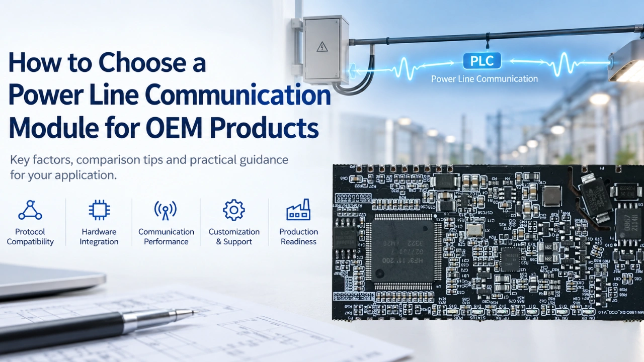
Choosing the right power line communication (PLC) module is an important step when adding data communication to an existing electrical product or developing a new connected device. The module must match the product’s communication protocol, electrical design, application environment, data requirements, and manufacturing goals.
For original equipment manufacturers (OEMs), selecting a PLC module involves more than comparing communication speeds or chip specifications. Engineers must also evaluate power-line signal coupling, hardware interfaces, electromagnetic compatibility (EMC), firmware integration, development support, and long-term product availability.
This guide explains how to choose a suitable power line communication module for OEM products, from defining application requirements to preparing for mass production.
What Is a Power Line Communication Module?
A power line communication module is an embedded communication component that transmits and receives digital data through existing electrical power conductors. Depending on its design, it may communicate over AC mains wiring, DC power lines, or a dedicated electrical network.
Unlike communication technologies that require separate data cables, PLC uses the power-line infrastructure as its communication medium. This can reduce additional communication wiring in suitable applications.
A PLC module can be integrated into products such as:
- Smart lighting controllers and LED drivers
- Industrial monitoring and control equipment
- Smart meters and energy management devices
- Solar lighting and power control systems
- Electrical cabinets and distribution equipment
- Building automation and infrastructure devices
- Embedded controllers and industrial IoT products
A PLC module is not necessarily a complete communication system by itself. Depending on the design, the final product may also require a coupling circuit, line driver, power supply, host MCU, firmware, protection components, and a gateway or network management platform.
1. Define Your OEM Product Requirements
Before comparing PLC modules, establish what the finished product needs to accomplish.
Start by answering these questions:
- What device will contain the PLC module?
- Will communication take place over AC mains, DC power lines, or another supported electrical network?
- What information must be transmitted?
- How many devices will communicate on the network?
- What communication distance and response time are required?
- Does the application require dimming, monitoring, remote control, or event reporting?
- What are the operating voltage, temperature, and environmental requirements?
- Will the module need to work with an existing gateway or communication platform?
For example, a smart LED driver may need to receive dimming commands and report voltage, current, power, and operating status. An industrial sensor may instead transmit alarm states and measurement data.
These applications may both use PLC, but their interface requirements, firmware, network behavior, and testing priorities can differ significantly.
Selection tip: Prepare a written requirements specification before choosing a module. This helps prevent expensive hardware redesigns later in development.
2. Check Communication Protocol Compatibility
Protocol compatibility is one of the most important factors when selecting a PLC module.
Different PLC solutions may use different physical-layer technologies, modulation methods, network protocols, and application-layer commands. Modules that all use power lines for communication are not automatically interoperable.
When comparing candidates, confirm the following:
- Supported PLC standards and protocol versions
- Physical-layer modulation and data rates
- Network topology and device addressing
- Network discovery and commissioning methods
- Error detection, retransmission, and security features
- Compatibility with the existing gateway, concentrator, and software platform
For example, IEEE 1901.1-based PLC solutions and other narrowband PLC technologies may have different implementation requirements. A module supporting one protocol should not be assumed to communicate with a device using another protocol without a compatible implementation.
Also distinguish between physical-layer compatibility and application-level interoperability. Two devices may use related communication technologies but still require compatible networking, command formats, firmware, and data models.
If your OEM product must connect to an existing PLC network, verify interoperability with the actual gateway and other network devices before committing to the design.
3. Evaluate Communication Performance Under Real Conditions
A module’s advertised data rate does not tell the whole story. Real-world performance depends on the electrical network, signal attenuation, electrical noise, coupling design, topology, and network traffic.
Evaluate these performance characteristics:
Communication data rate: Determine how much application data the product needs to send and receive. A monitoring sensor may have modest bandwidth requirements, while a controller handling frequent status updates across many devices may need a more carefully engineered network.
Communication distance: Check whether the module has been tested under conditions comparable to your application. Distance alone does not determine reliability because cable characteristics, branching, loads, and interference also affect the signal.
Network capacity: Consider the number of devices, simultaneous messages, polling frequency, and expected traffic. A network that works well with ten devices may behave differently with hundreds of endpoints.
Latency and reliability: Determine how quickly commands must be delivered and how the network handles packet errors, retries, and temporary interference.
Network commissioning: Check device discovery, addressing, reconnection behavior, and recovery after power interruptions.
For industrial and infrastructure applications, request test results from representative electrical networks rather than relying exclusively on laboratory data or theoretical maximums.
4. Verify Electrical Compatibility and Signal Coupling
A PLC module must match the electrical characteristics of the product into which it will be integrated.
Before selecting a module, verify:
- Operating voltage and power consumption
- AC or DC line compatibility
- Signal-coupling circuit requirements
- Line-driver requirements and supported components
- Isolation and electrical safety requirements
- Surge, transient, and overvoltage protection
- PCB layout and grounding recommendations
- Electromagnetic compatibility and immunity requirements
Signal coupling is particularly important. The PLC signal must be coupled onto the power line and recovered by the receiving circuit while maintaining the required electrical safety and signal quality.
Some modules integrate a line driver or provide a more complete communication front end. Others require external circuitry. This difference affects PCB space, component selection, development effort, and validation requirements.
Do not assume that a PLC module designed for one voltage range or power-line environment can be connected directly to another. Confirm the manufacturer’s reference design and electrical specifications before developing the hardware.
For products connected to mains electricity, the complete product must meet applicable electrical safety and isolation requirements. A communication module alone does not establish compliance for the finished equipment.
5. Select the Right Hardware Interface
The host interface determines how the PLC module exchanges data with the OEM product’s main controller.
Common interface options include:
| Interface | Typical use | Key consideration |
|---|---|---|
| UART | Embedded MCUs and control boards | Simple serial communication and firmware integration |
| SPI | Applications requiring a higher-speed host interface | Timing, driver support, and PCB routing |
| GPIO | Reset, status, interrupt, or control signals | Signal levels and pin configuration |
| PWM | Specific control or timing functions | Confirm the module’s supported functionality |
| ADC | Applications requiring analog measurements | Verify whether ADC functionality is available and suitable |
Not every module supports every interface. Always check the exact hardware and firmware documentation.
For OEM development, also ask whether the manufacturer provides communication command sets, interface documentation, reference code, example projects, and debugging tools.
A module with suitable hardware but incomplete documentation can increase engineering time and delay product launch.
6. Compare PLC Module Integration Options
PLC modules differ in how much circuitry and functionality they provide.
| Module type | Potential advantages | Considerations |
|---|---|---|
| PLC chipset or IC | Greater design flexibility and control | More responsibility for circuit design, firmware, and validation |
| Embedded PLC module | Can simplify integration into an existing PCB | Requires interface, power, and coupling compatibility checks |
| PLC communication board | May accelerate prototyping and evaluation | Size, connectors, and production integration may require redesign |
| Integrated PLC controller or device | May reduce system-level development effort | Less flexibility if the OEM needs a custom board or firmware architecture |
For an OEM product, an embedded PLC module can be a practical option when the development team wants to add power-line communication without designing every communication circuit from the ground up. Before starting, can first see our article How to Add PLC Communication to Existing Electrical Products for reference.
However, the best choice depends on production volume, board space, target cost, engineering resources, and required customization.
When comparing solutions, evaluate the total engineering and production cost rather than the module purchase price alone.
7. Assess Firmware, Software, and Customization Support
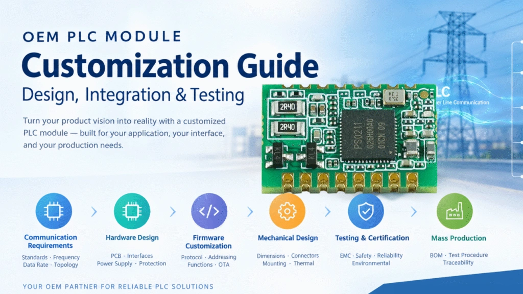
Hardware compatibility is only one part of a successful PLC integration project. The module must also work with the host product’s firmware and communication architecture. OEM PLC Module Customization Guide: Design, Integration & Testing this article is better for your guide.
Ask the supplier whether it provides:
- Host interface and protocol documentation
- Firmware examples and integration guidance
- Device discovery and network configuration support
- Diagnostic commands and troubleshooting tools
- Firmware updates and version management
- Custom firmware or hardware development
- Technical support during testing and deployment
Customization may be necessary when the OEM product has a special command structure, limited PCB space, unique power requirements, or an existing control platform.
Before development begins, define the customization scope, deliverables, test criteria, firmware responsibilities, and change-management process.
If the product needs to communicate with a gateway or cloud platform, clarify which functions are handled by the module, the host MCU, the gateway, and the application software. This separation helps avoid duplicated functions and unclear engineering responsibilities.
8. Consider Electromagnetic Interference and Environmental Conditions
Power lines are not always clean communication channels. Switching power supplies, LED drivers, motors, relays, converters, and other electrical loads can introduce noise or change the characteristics of the network.
For demanding applications, evaluate the module under realistic operating conditions.
Recommended checks include:
- Communication stability with representative electrical loads
- Performance during switching and dimming operations
- Noise immunity and recovery after interference
- Surge and transient protection
- Operation across the specified temperature range
- Performance on different cable lengths and network branches
- Behavior after repeated power cycles
For lighting applications, test the PLC module together with the actual LED driver or dimmer. A module that performs well on a bench may behave differently when integrated into the final power electronics.
In industrial applications, the test plan should reflect the real electrical environment and the relevant product-level EMC requirements.
9. Review Development Support and Mass-Production Readiness
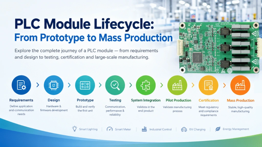
A suitable prototype does not automatically make a suitable mass-production solution. PLC Module Lifecycle: From Prototype to Mass Production this article may helpful for you to check.
OEM teams should assess the supplier’s ability to support the complete product lifecycle, including engineering samples, design validation, production testing, and ongoing supply.
Evaluate the following areas:
Technical documentation: Are specifications, pin definitions, reference circuits, and integration instructions available?
Engineering support: Can the supplier help troubleshoot communication problems and review the integration design?
Manufacturing consistency: Are production tests and quality-control procedures defined?
Product lifecycle: Is the module expected to remain available throughout the planned product lifetime? How are revisions and component changes communicated?
Customization and supply: Can the supplier support the required production volume, delivery schedule, and agreed customization scope?
Compliance documentation: Are the applicable component documents and test reports available, and what additional validation will the finished OEM product require?
A structured evaluation process helps reduce the risk of discovering integration or supply issues after the product design has already been finalized.
10. Use a Practical PLC Module Selection Checklist
Before choosing a module, review the following checklist with your engineering and purchasing teams.
- The PLC protocol is compatible with the intended network.
- The module supports the required AC or DC power-line environment.
- Communication performance has been evaluated under realistic conditions.
- The supported host interface matches the product’s MCU or controller.
- Power, coupling, protection, and PCB requirements are understood.
- Firmware, command documentation, and integration resources are available.
- The module fits the product’s size, thermal, and environmental constraints.
- Network capacity and device commissioning meet application requirements.
- The supplier can support testing, debugging, and customization.
- Production testing, lifecycle support, and supply requirements are defined.
- Product-level safety, EMC, and other applicable compliance requirements have been identified.
Use this checklist to compare candidate modules against the same requirements. It is more useful than choosing a product based on one headline specification.
Examples of PLC Module Selection for Different OEM Applications
The selection priorities change depending on the product being developed.
Smart lighting controllers and LED drivers
Prioritize communication compatibility with the lighting network, host interface support, dimming and status-reporting requirements, electrical noise performance, and integration with the LED driver’s power circuitry.
Industrial sensors and monitoring devices
Focus on reliable event reporting, host MCU compatibility, operating conditions, electrical protection, and the ability to communicate over the existing power network.
Smart meters and energy management equipment
Evaluate the required PLC protocol, interoperability, metering architecture, data throughput, security, and applicable industry requirements. The suitability of a module must be verified against the target system’s specifications.
Solar lighting and power control systems
Confirm compatibility with the actual electrical architecture, including the battery, power converter, controller, and lighting load. Do not assume that a PLC module can communicate through every power converter or isolated circuit without additional design work.
These examples illustrate why module selection should begin with the complete system architecture rather than a standalone component specification.
How MicroNature Supports OEM PLC Module Development
MicroNature develops power line communication solutions for smart lighting and other infrastructure applications. Its PLC module portfolio includes options designed for embedded integration and different system architectures.
For example:
- MN-L60C: A PLC module platform featuring an ARM Cortex-M4 and 32-bit DSP architecture, with interfaces including UART, PWM, and GPIO.
- MN-L80A: A PLC module based on the PS0211 platform, supporting IEEE P1901.1-related PLC technology and interfaces including UART, PWM, GPIO, ADC, SPI, and I2C.
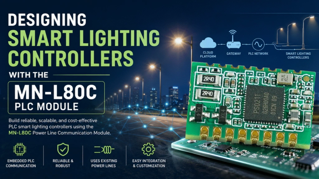
- MN-L80C: A PLC module based on the PS0211 platform, designed for embedded applications with IEEE P1901.1-related PLC technology and interfaces including UART, PWM, and GPIO.
Exact interface availability, firmware capabilities, electrical requirements, and supported operating conditions should be confirmed against the current datasheet for each model.
For OEM projects, the selection process should start by identifying the target application, power-line environment, required communication protocol, host interface, and customization needs. These requirements can then be matched to an appropriate module and validated through engineering samples and system-level testing.
Explore the MicroNature Power Line Communication Module catalog to review the available PLC module solutions.