Power Line Communication (PLC) allows electrical devices to exchange data through existing power lines instead of requiring a separate communication cable. For OEMs and electrical product manufacturers, this creates an opportunity to add remote monitoring, configuration, control, diagnostics, and networking capabilities to existing products.
The good news is that adding PLC communication does not necessarily mean redesigning the entire electrical product.
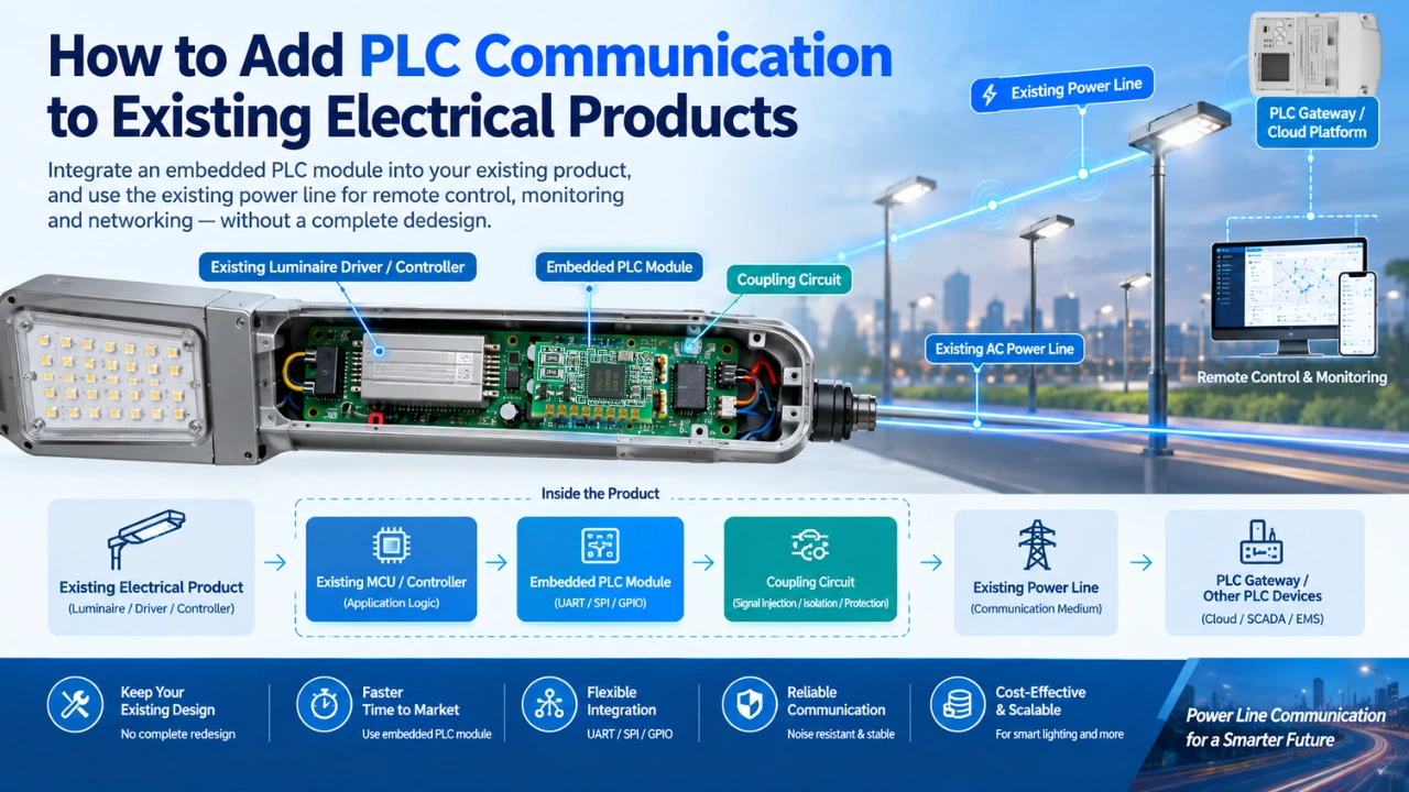
In many cases, an embedded PLC communication module can be integrated with the product’s existing MCU or controller through a standard interface such as UART or SPI. The PLC module handles power-line communication while the host controller continues managing the product’s main application functions.
This article explains a practical approach to adding PLC communication to an existing electrical product, from architecture and hardware integration to firmware development and production testing.
What Does It Mean to Add PLC Communication to an Existing Product?
An existing electrical product may already contain:
- A main MCU or processor
- Power supply
- Sensors
- Relays or MOSFETs
- Control interfaces
- Communication interfaces
- Product-specific application firmware
Adding PLC communication introduces another communication layer that allows the product to exchange data over its power connection.
A typical architecture looks like this:
Existing Electrical Product
→ Host MCU
→ Application firmware
→ Existing control functions
New PLC Communication Layer
→ PLC module
→ Coupling circuit
→ Power line
→ PLC network
The host MCU communicates with the PLC module, while the PLC module handles the physical and protocol-level communication over the electrical power line. For more information, can see IEEE 1901 standard.
This architecture allows manufacturers to add PLC connectivity while keeping much of their existing product design.
Why Use a PLC Module Instead of Designing PLC Hardware From Scratch?
For many OEM projects, developing the complete PLC communication circuit from the chipset level can significantly increase engineering time.
An embedded PLC module can simplify the integration process.
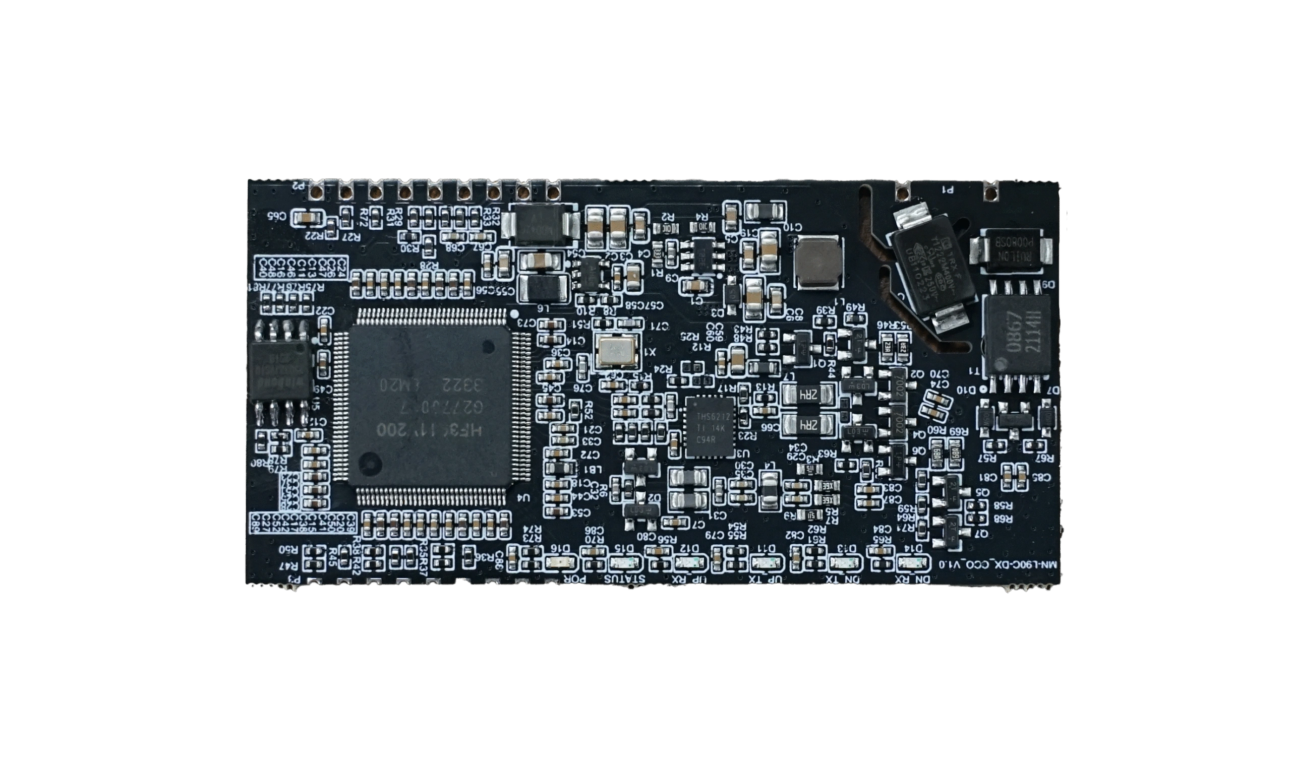
A typical PLC module may integrate:
- PLC modem/SoC
- MCU or processor
- PLC PHY
- Line driver
- Communication interface
- Power-line communication functions
- Supporting components
Depending on the module architecture, the host product may only need to provide:
- Power
- UART, SPI, or another supported interface
- Power-line coupling
- Firmware integration
This approach can reduce the amount of PLC-specific hardware development required by the OEM.
For example, MicroNature’s embedded PLC modules include models designed for integration with host controllers and provide interfaces such as UART, PWM, GPIO, ADC, SPI, or I²C, depending on the model.
Step 1: Identify the Existing Product Architecture
Before selecting a PLC module, first understand the existing electrical product.
Document the following:
1. Power input
Determine:
- AC or DC input
- Input voltage
- Frequency
- Maximum current
- Isolation requirements
- Power-supply topology
For example:
- 12 V DC controller
- 24 V industrial device
- 110/120 V AC equipment
- 220/230 V AC lighting equipment
- Three-phase electrical equipment
PLC integration requirements can vary significantly depending on the power architecture.
2. Existing MCU
Identify:
- MCU manufacturer
- MCU family
- CPU architecture
- Available GPIO
- UART interfaces
- SPI interfaces
- I²C interfaces
- Available memory
- Existing firmware architecture
The available host interface is particularly important when selecting a PLC module.
3. Available PCB space
Check:
- Module footprint
- Connector location
- Antenna requirements, if any
- Isolation distance
- High-voltage clearance
- Thermal conditions
- Mechanical enclosure limitations
A PLC module should be treated as part of the complete electrical design, not simply as another IC.
Step 2: Select the Appropriate PLC Module
The PLC module should be selected according to the actual application requirements.
Important parameters include:
| Parameter | Questions to Consider |
|---|---|
| PLC standard | Which PLC protocol or standard is required? |
| Data rate | How much data must be transmitted? |
| Interface | UART, SPI, GPIO, etc.? |
| Power supply | What voltage does the module require? |
| Network topology | Point-to-point, star, mesh, or other? |
| Communication distance | How far must devices communicate? |
| Noise environment | Is the power line electrically noisy? |
| Frequency band | Does it match the application requirements? |
| Firmware | What protocol/API does the module provide? |
| Certification | Which regional requirements apply? |
For example, an OEM developing a smart controller may prioritize a compact PLC module with UART communication, while an industrial product may require more interfaces and stronger noise immunity.
The key is to select the module based on the complete system, rather than simply choosing the module with the highest theoretical data rate.
Step 3: Connect the PLC Module to the Host MCU
One of the simplest architectures is:
Host MCU ↔ UART ↔ PLC Module ↔ Coupling Circuit ↔ Power Line
The existing MCU remains responsible for the application’s main functions.
The PLC module handles communication with other PLC devices.
For example, the host MCU may send a command such as:
Set Device ID = 1025The PLC module then transmits the corresponding communication packet through the power line.
A remote device can send data back through the same network.
This separation is useful because it keeps the application’s existing control logic relatively independent from the PLC communication layer.
Step 4: Integrate the PLC Coupling Circuit
The coupling circuit connects the PLC communication circuitry to the electrical power line.
This is one of the most important parts of PLC hardware design.
A simplified architecture is:
PLC Module
↓
Line Driver
↓
Coupling Network
↓
Power Line
The coupling circuit generally needs to address several requirements:
- Signal injection
- Signal extraction
- Voltage isolation where required
- Impedance matching
- Filtering
- Protection
- EMI considerations
- Surge protection
The exact coupling design depends on:
- PLC frequency band
- Power-line voltage
- AC/DC architecture
- Isolation requirements
- Target communication distance
- Regulatory requirements
- Noise environment
Therefore, a coupling circuit should not simply be copied from another product without checking whether its electrical conditions are compatible.
For a deeper technical explanation, see your planned/related article:
PLC Coupling Circuit Design Guide for Embedded Power Line Communication Devices
Step 5: Consider Power Supply and Isolation
Adding a PLC module changes the electrical architecture of the product.
The module may require a dedicated low-voltage power supply.
For example:
AC mains
→ Power supply
→ 12 V / 5 V / 3.3 V
→ PLC module
At the same time, the PLC signal may need to be coupled to the power line.
Engineers should carefully evaluate:
- Creepage distance
- Clearance
- Isolation barrier
- Grounding
- Common-mode noise
- Surge protection
- ESD protection
- EFT/burst immunity
- Lightning/surge environment
This becomes particularly important for industrial and outdoor products.
Step 6: Integrate PLC Functions Into Existing Firmware
Hardware integration is only part of the project.
The host firmware also needs to communicate with the PLC module.
A practical software architecture is:
Application Layer
↓
PLC Communication API
↓
UART/SPI Driver
↓
PLC Module
The existing application can then call simple functions such as:
PLC_Send()
PLC_Receive()
PLC_SetAddress()
PLC_GetStatus()
PLC_ReadNode()
PLC_WriteNode()
The actual API depends on the PLC module and communication protocol.
A good software architecture should separate PLC communication from the product’s core application logic.
This makes it easier to:
- Debug the system
- Replace the communication module
- Update the PLC protocol
- Add new commands
- Maintain existing firmware
Step 7: Define the Data Protocol
Before mass production, define what information the electrical product needs to exchange over the PLC network.
For example, an industrial controller might transmit:
- Device ID
- Operating status
- Voltage
- Current
- Temperature
- Energy consumption
- Alarm status
- Configuration parameters
A simple communication structure could be:
Device ID
↓
Command
↓
Data Length
↓
Data
↓
Checksum
For a lighting controller, the data might include:
Lamp ID
Brightness
Voltage
Current
Power
Energy
Fault Status
For another electrical product, the payload can be completely different.
The important principle is that PLC provides the communication channel; the OEM defines the application data.
Step 8: Test PLC Communication in the Real Electrical Environment
A PLC module that communicates successfully on a development bench may behave differently inside the final product.
This is because the actual electrical product contains:
- Switching power supplies
- Motors
- Relays
- Inverters
- LEDs
- Capacitors
- Filters
- Transformers
- Other electronic loads
These components can introduce significant electrical noise.
Testing should therefore be performed with the actual product hardware, not only with a laboratory PLC test board.
Important tests include:
Communication distance
Test the maximum practical communication distance under realistic wiring conditions.
Packet loss
Measure communication reliability over repeated transmissions.
Electrical noise
Test while major switching components are operating.
Startup and shutdown
Check whether PLC communication remains stable during:
- Power-on
- Power-off
- Restart
- Load switching
Network scalability
Test multiple devices simultaneously.
Long-duration operation
Run the PLC network continuously to identify intermittent communication problems.
Step 9: Test Different Loads
Electrical loads can strongly influence PLC communication performance.
For example, test the system with:
- Normal load
- Maximum load
- Minimum load
- Switching loads
- Motor loads
- LED drivers
- Power supplies
- Inductive loads
The objective is to verify that the PLC signal remains reliable under the conditions that the final product will actually experience.
This is particularly important for industrial PLC applications.
Step 10: Optimize PCB Layout
PLC integration also requires careful PCB layout.
Keep high-voltage and low-voltage sections appropriately separated.
Pay attention to:
- PLC signal paths
- Coupling components
- High-current traces
- Switching nodes
- Ground planes
- Isolation barriers
- Protection components
- EMI-sensitive circuits
Avoid placing sensitive PLC circuitry immediately beside high-frequency switching components whenever possible.
The final PCB should be evaluated as a complete EMC system rather than treating the PLC module as an isolated component.
PLC Integration Example
Consider an existing industrial lighting controller.
The original design contains:
MCU → LED driver → Lamp
The manufacturer wants to add remote control and monitoring.
Instead of redesigning the complete controller, the manufacturer can add:
MCU ↔ PLC Module ↔ Coupling Circuit ↔ Power Line
The existing MCU can continue controlling:
- LED brightness
- ON/OFF operation
- Sensors
- Local protection
The PLC module adds communication between the controller and the central gateway.
The resulting architecture can support functions such as:
- Remote ON/OFF
- Dimming
- Device addressing
- Energy monitoring
- Fault reporting
- Remote configuration
- Scheduled control
This approach can be particularly useful when the existing electrical wiring is already available and installing new communication cables would be expensive or impractical.
Can PLC Be Added Without Changing the Existing MCU?
Sometimes, yes.
If the existing product already has an available UART, SPI, or other compatible interface, integration can often be relatively straightforward.
However, if the MCU has no available communication interface, limited memory, or insufficient processing resources, additional hardware or firmware changes may be necessary.
Possible approaches include:
Option 1: Use an existing UART
Usually the simplest architecture.
Option 2: Use SPI
Useful when higher-speed host-module communication is required.
Option 3: Add a secondary MCU
This can separate PLC communication from the original application controller.
Option 4: Replace the existing controller
This may be necessary when the original MCU cannot provide sufficient resources.
The appropriate solution depends on the existing product architecture.
Common Challenges When Adding PLC Communication
1. Electrical Noise
Noise from switching power supplies, motors, and LED drivers can reduce communication reliability.
Solution: Evaluate the PLC signal under real operating conditions and optimize filtering, coupling, PCB layout, and firmware retry mechanisms.
2. Insufficient PCB Space
Existing products may have little room for additional hardware.
Solution: Use a compact embedded PLC module and integrate it directly into the PCB or through a compact connector.
3. Firmware Compatibility
Existing firmware may not have been designed for networking.
Solution: Add a dedicated PLC communication layer between the application and hardware drivers.
4. Power-Line Attenuation
Long cables and different loads can weaken PLC signals.
Solution: Test the actual electrical network and evaluate network topology, coupling design, and signal quality.
5. EMC and Safety Requirements
Adding communication circuitry can affect the product’s EMC and electrical safety performance.
Solution: Include EMC, surge, ESD, isolation, and safety considerations from the beginning of the integration process.
PLC Integration Checklist for OEM Engineers
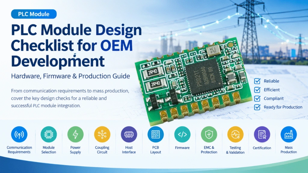
If you are a new user, can first see this article PLC Module Design Checklist for OEM Development | Hardware & Testing. Before moving to mass production, verify:
Hardware
- PLC module selected
- Host MCU interface confirmed
- Module power supply verified
- Coupling circuit designed
- Protection circuit evaluated
- PCB clearance and isolation checked
- Thermal requirements checked
Firmware
- PLC driver integrated
- Communication protocol defined
- Device addressing implemented
- Error handling implemented
- Timeout/retry mechanism implemented
- Configuration commands implemented
- Remote diagnostics implemented if required
Testing
- Communication distance tested
- Packet loss measured
- Multiple nodes tested
- Maximum electrical load tested
- Switching noise tested
- Power-cycle testing completed
- Long-duration communication tested
- EMC testing planned/completed
- Production test procedure defined
PLC Module vs. Developing PLC Hardware From Scratch
| Approach | PLC Module | Develop From Scratch |
|---|---|---|
| Development time | Generally shorter | Generally longer |
| Hardware complexity | Lower | Higher |
| Initial engineering effort | Lower | Higher |
| Customization | Depends on module | Very high |
| Firmware work | Module/API integration | Full PLC development |
| PCB design | Simpler | More complex |
| Testing requirements | Reduced | Extensive |
| Best suited for | OEM integration | High-volume/custom PLC platforms |
For manufacturers that need a customized PLC solution but do not want to develop the complete PLC communication stack themselves, a configurable embedded PLC module can provide a middle ground between a standard communication chip and a completely custom PLC design.
When Should You Add PLC Communication to an Existing Product?
PLC integration can be considered when a product needs communication but installing new communication cables is difficult or expensive.
Typical applications include:
- Smart lighting controllers
- Industrial control equipment
- Energy meters
- Emergency lighting
- Power distribution equipment
- EV charging equipment
- Solar power equipment
- Building automation devices
- Motor controllers
- Industrial sensors
- Pump and HVAC controllers
- Smart electrical cabinets
The strongest application case is often a system where the electrical power wiring already exists and can also serve as the communication medium.
How MicroNature Supports PLC OEM Integration
For OEMs developing PLC-enabled electrical products, MicroNature provides embedded PLC communication modules and related hardware for integrating Power Line Communication into existing products.
The integration approach can be adapted to different product architectures, including:
- Host MCU + PLC module
- UART-based PLC integration
- SPI-based PLC integration
- PLC coupling circuits
- PLC gateways and concentrators
- Single-device PLC controllers
- Industrial PLC communication systems
- Smart lighting controllers
For example, the MN-L80C PLC module is designed for embedded applications and can provide PLC communication capabilities through host interfaces such as UART, PWM, and GPIO.
For projects requiring customized hardware or firmware, an OEM integration process can include:
Product architecture review → PLC module selection → Hardware integration → Coupling design → Firmware/API integration → Prototype → Communication testing → EMC validation → Mass production
This approach allows manufacturers to add PLC communication while preserving as much of their existing electrical product architecture as possible.