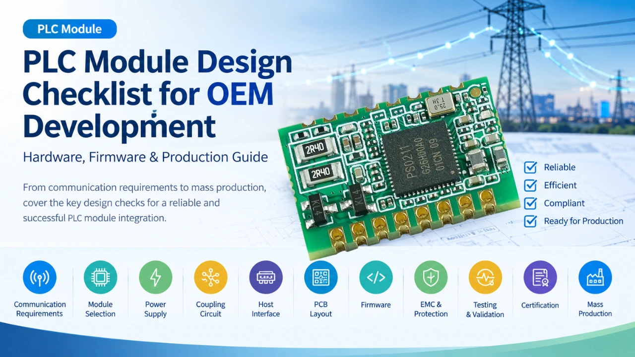
Designing an OEM product around a PLC (Power Line Communication) module involves more than connecting a communication module to a host MCU. Engineers need to consider the PLC physical layer, coupling circuit, power supply, host interface, firmware, electromagnetic compatibility, protection, testing, certification, and mass production requirements.
A well-defined design checklist can help OEM teams identify technical risks before PCB design, prototype testing, and production.
This guide provides a practical PLC module design checklist for OEM development, from initial requirements through mass production.
What Should Be Checked When Designing an OEM Product with a PLC Module?
Before integrating a PLC module into an OEM product, verify these key areas:
- PLC communication requirements
- PLC module selection
- Power supply design
- PLC coupling circuit
- Host MCU interface
- PCB and grounding design
- Firmware and protocol integration
- EMC and noise immunity
- Electrical protection
- Communication performance testing
- Product certification
- Production and manufacturing requirements
The earlier these items are defined, the lower the risk of redesign during prototype and mass-production stages.
1. Define the PLC Communication Requirements
The first step is to define what the PLC network must actually accomplish.
Do not select a PLC module only according to its advertised communication speed. The module should be matched to the electrical environment, network topology, application protocol, and required communication reliability.
PLC communication checklist
| Requirement | Questions to Check |
|---|---|
| Communication medium | AC power line, DC power line, or other wired power network? |
| Network type | Single-phase or three-phase? |
| Communication distance | What is the required maximum distance? |
| Data rate | What throughput is required? |
| Network topology | Point-to-point, bus, tree, or mesh? |
| Node count | How many PLC devices will operate on one network? |
| Response time | Is real-time or near-real-time communication required? |
| Noise environment | Are motors, drives, relays, switching power supplies, or other noise sources present? |
| Protocol | Proprietary protocol or standardized PLC protocol? |
| Reliability | What packet loss, retry, and availability requirements exist? |
For industrial and infrastructure applications, the electrical environment can be significantly more challenging than a laboratory test environment. Communication performance should therefore be evaluated under realistic load and noise conditions.
2. Select the Appropriate PLC Module
The PLC module is the core communication component of the OEM design.
The selection should consider not only the PLC PHY but also the module’s processor architecture, host interfaces, software support, operating environment, and long-term supply capability. If you are comparing different levels of PLC hardware, see our guide to PLC Module vs PLC Chipset vs PLC Board: What’s the Difference?
PLC module selection checklist
- PLC standard or communication technology identified
- Supported frequency band verified
- PHY data rate meets application requirements
- Communication distance evaluated
- Network topology supported
- Host interface supported
- Required GPIO/PWM/ADC functions available
- Operating voltage compatible with the OEM system
- Operating temperature meets product requirements
- Module dimensions fit the PCB
- Firmware/API documentation available
- Development samples available
- Production supply capability confirmed
- Customization requirements discussed with the module supplier
For embedded applications, an OEM should also determine whether the PLC module includes the necessary line driver, communication processing, and interface functions, or whether additional external components are required.
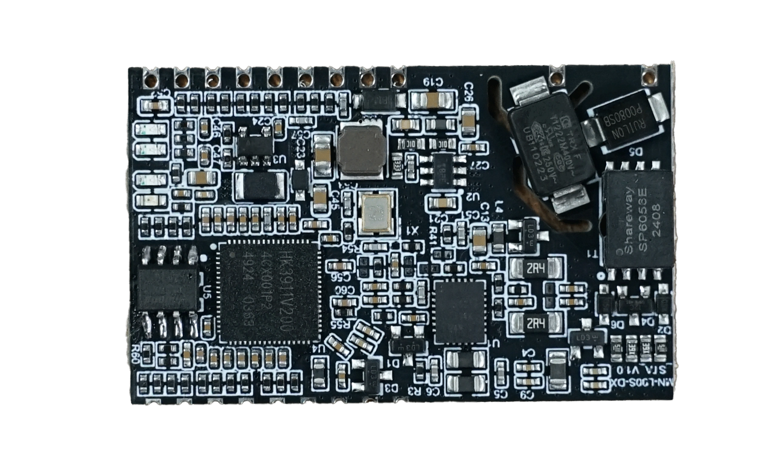
For example, MicroNature’s PLC module portfolio includes embedded PLC communication modules designed for integration with host controllers and industrial equipment.
3. Check the Power Supply Design
PLC communication hardware is sensitive to power integrity.
A poorly designed power supply can introduce noise into the PLC communication path and reduce communication stability.
Check:
- Input voltage range
- Module operating voltage
- Peak current consumption
- Standby current
- Startup sequence
- DC/DC converter selection
- LDO requirements
- Power filtering
- Decoupling capacitors
- Ground return path
- Power supply noise
- Transient conditions
The power supply should be evaluated under both normal operation and worst-case conditions.
Particular attention should be given to products containing:
- Motors
- Relays
- LED drivers
- Switching power supplies
- Inverters
- Variable-frequency drives
- High-current loads
These devices can introduce electrical noise that affects PLC communication. Before starting project, please first see our article PLC Signal Noise Troubleshooting Guide: Causes & Solutions for reference.
4. Design and Verify the PLC Coupling Circuit
The PLC coupling circuit is one of the most important parts of an embedded PLC design.
It provides the interface between the PLC transceiver and the power line while helping isolate the communication signal from unsuitable voltage and transient conditions.
Depending on the application, the coupling design may include:
- Coupling capacitors
- Transformers
- Inductors
- Filters
- Protection components
- Impedance-matching components
- Isolation components
- Surge protection
Coupling circuit checklist
- Coupling topology selected
- Component voltage rating verified
- Current rating verified
- Frequency response evaluated
- PLC signal attenuation measured
- Line impedance considered
- Surge conditions evaluated
- Isolation requirements evaluated
- PCB creepage and clearance checked
- Protection components selected
- Coupling circuit tested under real load conditions
The coupling circuit should not be treated as an isolated schematic block. Its interaction with the actual power line, load, filters, and protection circuitry can significantly affect PLC performance.
For more detailed engineering considerations, see the PLC Coupling Circuit Design Guide for Embedded Power Line Communication Devices.
5. Verify the Host Interface
The PLC module must communicate reliably with the OEM host controller.
Common interfaces include:
- UART
- SPI
- GPIO
- PWM
- ADC
- I²C
The correct interface depends on the module and application architecture.
Host interface checklist
- Electrical voltage levels compatible
- Communication speed sufficient
- Pin assignment confirmed
- Interrupt requirements defined
- Reset behavior defined
- Boot sequence documented
- Error handling implemented
- Flow control requirements checked
- Communication protocol documented
- Firmware driver available
- Interface tested under high communication load
For example, an OEM controller may use UART to communicate with a PLC module while the host MCU manages application logic, sensors, relays, or lighting control. Explore MicroNature PLC Communication Modules →MN-L80C Power Line Communication (PLC) Module | IEEE P1901.1 OFDM Module.
6. Plan the PCB Layout Carefully
A PLC module can perform well on a development board but experience problems after being integrated into an OEM PCB.
PCB layout can affect:
- PLC signal integrity
- EMC performance
- Noise coupling
- Power integrity
- Grounding
- Thermal performance
- Protection performance
PCB design checklist
- PLC module placement optimized
- Coupling circuit located appropriately
- High-noise components separated from PLC circuitry
- Switching power supply kept away from sensitive communication circuits
- Grounding strategy defined
- High-current traces separated from signal paths
- Short and controlled signal paths used where appropriate
- Decoupling capacitors placed close to relevant pins
- Creepage and clearance requirements satisfied
- Thermal requirements considered
Special attention should be paid when the PLC module is installed in products containing high-power switching circuits.
7. Define the Firmware Architecture
Hardware integration is only part of the OEM development process.
The host firmware must properly manage the PLC module and application protocol.
A typical architecture may look like:
Application Layer → Host MCU → PLC Driver → PLC Module → Coupling Circuit → Power Line
The firmware should define how the system handles:
- Device initialization
- PLC network joining
- Address assignment
- Data transmission
- Data reception
- Retransmission
- Timeout
- Communication errors
- Device discovery
- Configuration
- Firmware upgrades
- Diagnostics
Firmware checklist
- PLC driver implemented
- Initialization sequence tested
- Communication state machine defined
- Timeout mechanism implemented
- Retry mechanism implemented
- Error codes defined
- Network discovery implemented if required
- Device addressing defined
- Configuration storage implemented
- Remote update strategy considered
- Communication logs available for debugging
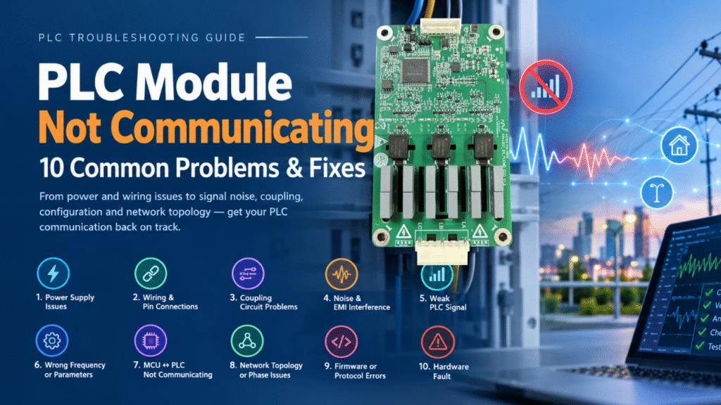
A clear separation between the PLC communication layer and the OEM application layer can also make future product development easier. If communication problems occur during integration, see PLC Module Not Communicating? 10 Common Problems & Fixes.
8. Consider EMC and Electrical Noise
EMC should be considered from the beginning rather than treated as a final certification step.
PLC communication intentionally uses the power line as the communication medium. However, the same power line can contain electrical noise from other equipment.
Potential interference sources include:
- Switching power supplies
- LED drivers
- Motors
- Inverters
- Relays
- Contactors
- Industrial equipment
- Long power cables
- Other communication devices
EMC checklist
- Conducted emissions evaluated
- Radiated emissions evaluated
- Conducted immunity evaluated
- Radiated immunity evaluated
- EFT/burst evaluated
- Surge tested
- ESD tested
- PLC communication tested during EMC events
- Noise filtering evaluated
- Communication recovery verified
The important question is not simply whether the OEM product passes an EMC test.
It should also be verified whether PLC communication remains stable during and after electrical interference.
9. Add Electrical Protection
OEM equipment connected directly or indirectly to power lines may be exposed to electrical transients.
Depending on the product architecture and installation environment, protection may be required against:
- Surge
- ESD
- EFT
- Overvoltage
- Overcurrent
- Short circuit
- Reverse polarity
- Lightning-related transients
Protection checklist
- Surge protection selected
- ESD protection selected
- Overvoltage protection evaluated
- Overcurrent protection evaluated
- Thermal protection evaluated
- Protection component ratings verified
- Protection coordination checked
- Worst-case transient testing completed
Protection components should be selected based on the actual electrical environment rather than simply copied from a reference design.
10. Test PLC Communication Performance
Communication testing should cover both ideal laboratory conditions and real application environments.
Basic PLC performance tests
| Test | Purpose |
|---|---|
| Communication distance | Verify maximum practical range |
| Packet loss | Evaluate communication reliability |
| Throughput | Verify data transmission capacity |
| Latency | Measure communication response |
| Network discovery | Verify device joining and addressing |
| Multi-node communication | Test network scalability |
| Retry performance | Evaluate recovery from packet loss |
| Noise testing | Evaluate performance under interference |
| Load testing | Verify communication during maximum system load |
| Long-duration test | Identify intermittent failures |
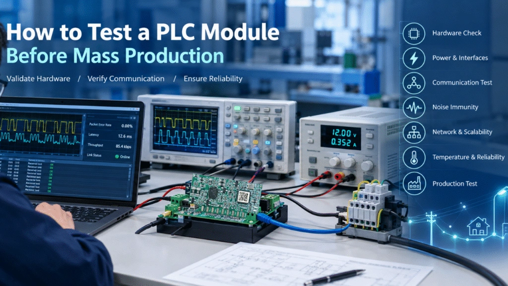
For an OEM product, it is particularly important to test the PLC module after integration into the final PCB and enclosure. For a more detailed prototype validation procedure, see our guide to How to Test a PLC Module Before Mass Production.
A module that passes a standalone test does not automatically guarantee the same performance after integration.
11. Test Different Power-Line Conditions
PLC performance can vary considerably depending on the electrical network.
Test conditions should include, where applicable:
- Different cable lengths
- Different cable types
- Different loads
- Different load combinations
- Different power supplies
- Different circuit breakers
- Different filters
- Different line impedances
- High-noise conditions
- Low-signal conditions
- Multiple PLC nodes
For three-phase systems, testing should also verify communication across the intended phases and through the actual coupling architecture.
This is especially important for industrial lighting, street lighting, tunnels, factories, warehouses, and other infrastructure applications.
12. Verify Operating Temperature and Reliability
OEM products may operate outdoors, inside electrical cabinets, or in industrial environments.
The PLC module should therefore be evaluated under the expected environmental conditions.
Environmental checklist
- Operating temperature verified
- Storage temperature verified
- Humidity requirements checked
- Thermal cycling tested
- Long-duration operation tested
- Vibration requirements evaluated
- Mechanical shock evaluated if required
- Enclosure/IP requirements considered
- Component lifetime evaluated
For outdoor lighting applications, the PLC communication system should also be tested together with the actual lamp driver, controller, enclosure, and power network.
13. Plan Certification and Compliance
Certification requirements depend on the target market, product category, voltage level, installation environment, and communication technology.
Before mass production, identify the applicable requirements for the target market.
Potential areas include:
- EMC
- Electrical safety
- Environmental requirements
- Radio/communication requirements where applicable
- RoHShttps://www.rohsguide.com/
- Other regional compliance requirements
The OEM should determine certification responsibility early.
Ask:
Who is responsible for certification—the PLC module supplier or the OEM product manufacturer?
Module-level compliance does not necessarily mean that the complete OEM product automatically satisfies every applicable requirement.
14. Check Manufacturing and Supply-Chain Requirements
A technically successful prototype still needs to be suitable for mass production.
Production checklist
- BOM finalized
- Critical components identified
- Component lifecycle checked
- Alternative components evaluated
- PCB manufacturing process confirmed
- SMT assembly requirements confirmed
- Programming method defined
- Production test fixture designed
- Functional test procedure documented
- PLC communication test procedure documented
- Serial number strategy defined
- Calibration procedure defined if required
- Traceability requirements defined
- Firmware version control established
The PLC module supplier should also be able to provide a stable supply plan for the expected production period.
15. Design a Production Test Strategy
Production testing should detect failures that may not be visible through visual inspection.
A typical PLC-enabled OEM product may require tests for:
- Power supply
- Host MCU
- PLC module
- PLC communication
- Input/output functions
- Sensors
- Relays or dimming functions
- Firmware version
- Configuration
- Final functional operation
For higher-volume products, automated production test equipment can reduce test time and improve consistency.
16. Verify the Complete System, Not Only the PLC Module
One of the most important principles in PLC OEM development is:
Test the complete system, not only the communication module.
A PLC module may perform correctly when tested independently but behave differently after integration because of:
- PCB layout
- Power supply noise
- Coupling circuit
- EMI filters
- LED drivers
- Motors
- Relays
- Enclosure
- Grounding
- Cable length
- Other electronic devices
Therefore, final validation should use the actual OEM hardware whenever possible.
17. PLC Module OEM Development Checklist
The following condensed checklist can be used during an OEM design review.
Requirements
- Application requirements defined
- Communication distance defined
- Data rate defined
- Node count defined
- Network topology defined
- Electrical environment evaluated
PLC Module
- Suitable PLC technology selected
- Module performance verified
- Operating voltage verified
- Temperature range verified
- Host interface verified
- Documentation available
- Supply availability confirmed
Hardware
- Power supply designed
- PLC coupling circuit designed
- Protection circuit designed
- PCB layout reviewed
- Grounding strategy defined
- Thermal design verified
Firmware
- Host driver implemented
- Communication protocol defined
- Initialization sequence tested
- Error handling implemented
- Retry mechanism implemented
- Diagnostics implemented
- Firmware update strategy defined
Testing
- Communication distance tested
- Throughput tested
- Latency tested
- Packet loss tested
- Multi-node operation tested
- Noise environment tested
- Long-duration operation tested
- Environmental testing completed
EMC & Compliance
- EMC pre-test completed
- Surge tested
- ESD tested
- EFT tested
- Applicable safety requirements identified
- Regional certification requirements identified
Production
- BOM finalized
- Production test procedure defined
- Test fixture prepared
- Programming process defined
- Firmware version control established
- Component supply verified
- Mass-production validation completed
18. When Should an OEM Consider a Custom PLC Module?
A standard PLC module is often the fastest way to develop a prototype. However, a customized PLC module may make sense when the OEM has specific requirements.
Examples include:
- Special PCB dimensions
- Custom connectors
- Custom host interfaces
- Specific power requirements
- Integrated sensors
- Integrated protection
- Customized firmware
- Customized communication protocols
- Special environmental requirements
- High-volume production
A customized module can reduce the number of external components and simplify the OEM product architecture.
However, customization should be evaluated against development cost, production volume, certification requirements, and expected product lifetime.
19. Standard Module vs. Custom PLC Module
| Factor | Standard PLC Module | Custom PLC Module |
|---|---|---|
| Development speed | Faster | Slower |
| Initial cost | Lower | Higher |
| Hardware flexibility | Moderate | High |
| PCB integration | Good | Optimized |
| Custom interface | Limited | Flexible |
| Firmware customization | Depends on supplier | High |
| Prototype development | Recommended | Suitable for specific requirements |
| High-volume OEM | Suitable | Often attractive |
| Special application | May require external components | Can be optimized |
For many OEM projects, the most efficient approach is to start with a standard PLC module for proof of concept and then evaluate customization after the communication architecture has been validated.
20. Key Questions to Ask a PLC Module Supplier
Before selecting a PLC module supplier, OEM engineers should ask:
Hardware
- What PLC technology does the module use?
- What is the typical communication distance?
- What host interfaces are available?
- Is the line driver integrated?
- What external coupling components are required?
- What operating temperature range is supported?
Software
- Is a host-side SDK or driver available?
- Is the communication protocol documented?
- Can the firmware be customized?
- Is remote firmware updating supported?
- Are diagnostic functions available?
Testing
- What PLC performance tests have been completed?
- Has the module been tested in industrial environments?
- What EMC tests have been performed?
- Are reference designs available?
- Can the supplier support OEM validation?
Production
- What is the minimum order quantity?
- What is the expected lead time?
- How long will the module remain available?
- Are component substitutions controlled?
- Can the supplier support customized hardware or firmware?
These questions help OEM teams evaluate not only the module itself but also the supplier’s ability to support the complete product lifecycle.