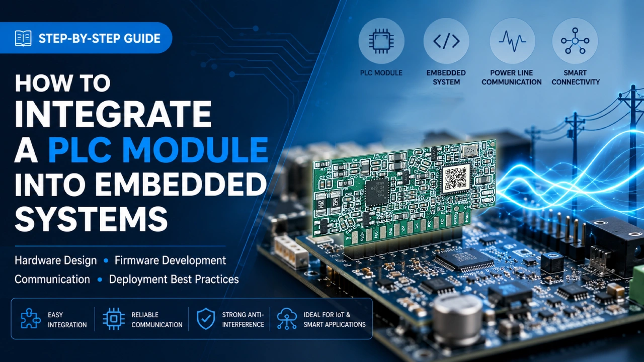
PLC module integration is becoming an essential skill for embedded system developers building smart lighting, industrial IoT, smart metering, and energy management devices. As IoT devices continue to expand into smart cities, industrial automation, energy management, and intelligent lighting, reliable communication becomes increasingly important. While wireless technologies like Wi-Fi, Zigbee, LoRaWAN, and NB-IoT are widely used, Power Line Communication (PLC) provides another compelling option by transmitting data through existing power cables.
For embedded system developers, integrating a PLC communication module offers an efficient way to build connected products without adding new communication wiring.
This guide explains the complete integration process—from hardware selection and PCB design to firmware development and network deployment—helping engineers successfully incorporate PLC modules into embedded systems.
Why Integrate PLC Modules?
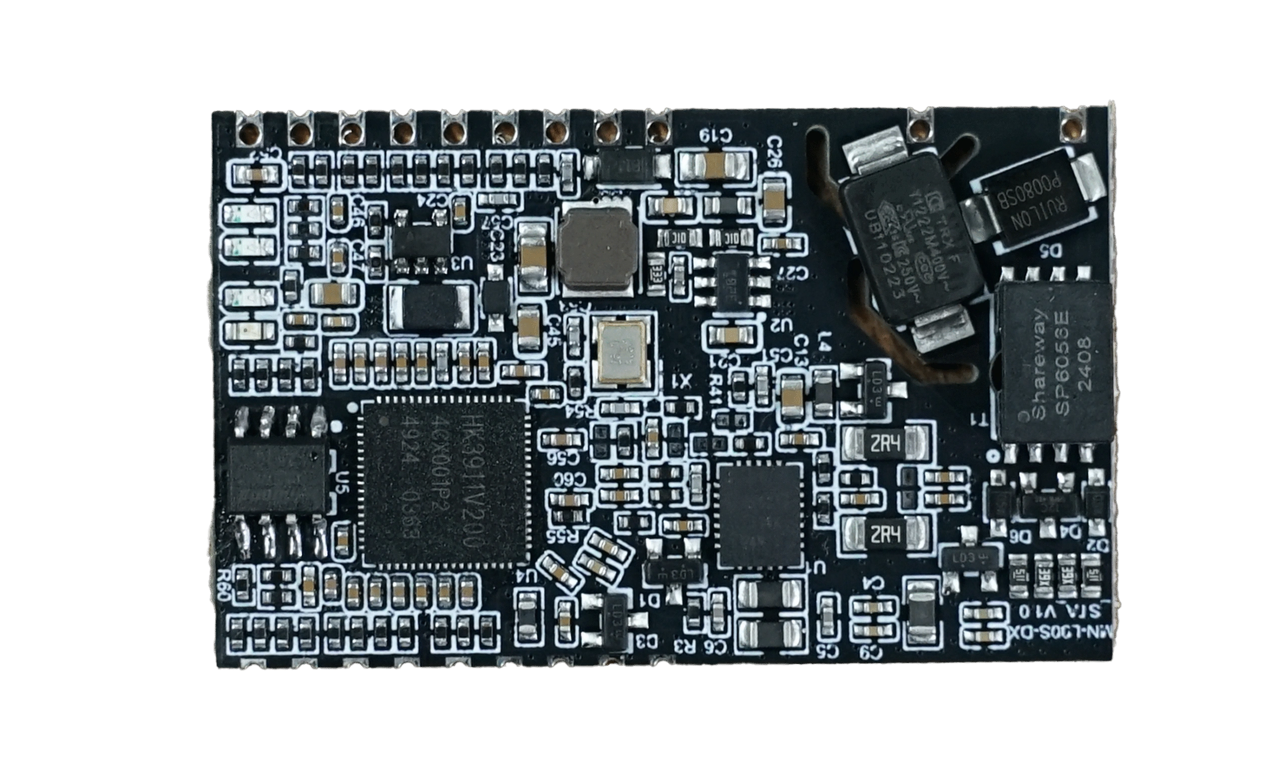
Unlike standalone PLC chipsets, PLC modules already integrate the RF front-end, analog circuitry, filtering network, clock, memory, and communication protocol stack. Developers only need to connect the module with their host MCU.
This significantly reduces:
- Hardware development complexity
- EMC certification challenges
- Firmware development time
- Product development cost
- Time-to-market
Instead of designing an entire PLC communication circuit from scratch, manufacturers can focus on their application software.
ypical Embedded System Architecture
A typical embedded PLC system consists of several functional blocks.
Application Software
        │
Host MCU / MPU
        │
UART / SPI / Ethernet
        │
PLC Communication Module
        │
Power Line Coupling Circuit
        │
AC Power Network
        │
Other PLC Devices
The host controller manages application logic while the PLC module handles communication across the power line.
Step 1: Choose the Right PLC Module
The first step is selecting a PLC module suitable for your application.
Consider the following factors:
Communication Interface
Most PLC modules support:
- UART
- SPI
- Ethernet
- RS-485 (some industrial models)
Choose one that matches your processor.
Network Topology
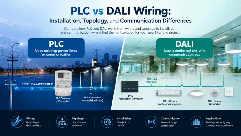
Different applications require different network architectures. If you are a new user, feel free to read our article PLC Smart Lighting System Architecture Guide.
Examples include:
- Point-to-point
- Star network
- Mesh network
- Multi-hop routing
Street lighting systems generally benefit from self-healing mesh networking.
Communication Distance
Evaluate:
- Cable length
- Number of nodes
- Transformer crossing requirements
- Noise level
- Required communication speed
Industrial environments often require stronger anti-interference capabilities than residential applications.
Environmental Conditions
Choose modules designed for:
- High EMI environments
- Outdoor temperature ranges
- High humidity
- Electrical surges
- Long operating lifetimes
Step 2: Design the Hardware Interface
Hardware integration is usually straightforward because most PLC modules expose standard interfaces.
Typical connections include:
| Signal | Description |
|---|---|
| UART TX/RX | Serial communication |
| SPI | High-speed communication |
| RESET | Module reset |
| GPIO | Status indication |
| Power Supply | 3.3V or 5V |
| Ground | Common reference |
Proper PCB layout is essential for communication stability.
Recommendations include:
- Keep communication traces short.
- Separate digital and power circuits.
- Use solid ground planes.
- Follow the manufacturer’s layout guide.
- Place decoupling capacitors close to the module.
Step 3: Design the Power Line Coupling Circuit
The coupling circuit connects the PLC signal to the AC power line while maintaining electrical isolation.
Typical components include:
- Isolation transformer
- Coupling capacitor
- Protection resistor
- MOV surge protection
- EMI filter
- Common mode choke
A well-designed coupling circuit greatly improves communication reliability.
Step 4: Develop Embedded Firmware
Once the hardware is operational, firmware integration begins.
The host MCU typically performs tasks such as:
- Module initialization
- Network configuration
- Device registration
- Data packet transmission
- Packet reception
- Error handling
- Firmware upgrades
- Diagnostic logging
Many PLC modules provide SDKs or AT-style command sets that simplify firmware development.
Step 5: Implement Communication Protocols
Most embedded applications use layered communication protocols. Modern PLC modules typically implement standardized PHY and MAC layers based on industry specifications such as the IEEE power line communication standards, ensuring interoperability and reliable data transmission across power networks.
Example architecture:
Application Layer
Device Management
Network Layer
PLC MAC Layer
PLC PHY Layer
Power Line
The application usually exchanges structured packets such as:
- Lighting commands
- Sensor values
- Energy data
- Fault alarms
- Device status
- Firmware update packets
Reliable packet acknowledgement and retransmission improve communication robustness.
Step 6: Optimize Network Performance
Large PLC deployments require careful optimization.
Key considerations include:
Address Management
Each device should have a unique network address.
Routing
Mesh routing enables automatic path selection if one communication route fails.
Retry Mechanism
Communication errors should trigger automatic retransmission.
Noise Immunity
Industrial environments generate electrical noise from:
- Motors
- Variable frequency drives
- Switching power supplies
- Large machinery
Advanced PLC modules use adaptive modulation and error correction to maintain stable communication.
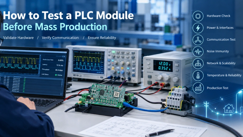
Step 7: Test Before Deployment
Comprehensive testing helps ensure long-term reliability. How to Design a PLC Smart Lighting Network is an important thing before project start.
Recommended tests include:
- Communication range
- Packet loss
- Response latency
- Multi-node networking
- Power interruption recovery
- Surge immunity
- Long-duration stability
- Temperature testing
Field testing under real operating conditions is strongly recommended before mass production.
Common Embedded Applications
PLC modules are widely integrated into embedded products such as:
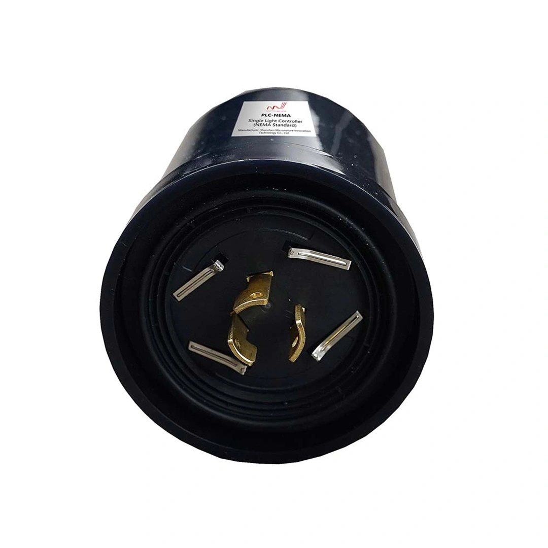
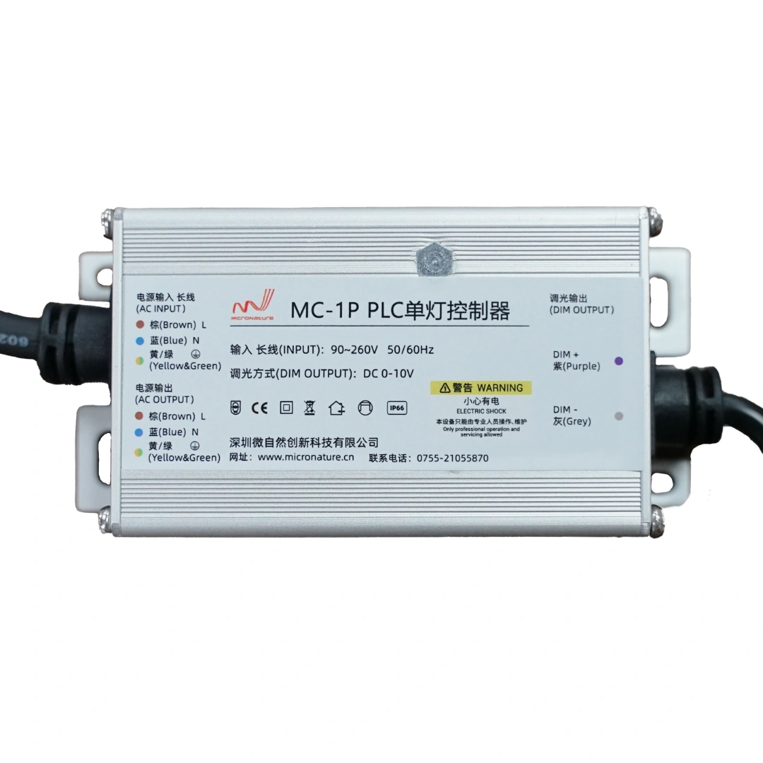
- Smart street lighting controllers
- Industrial lighting systems
- Smart buildings
- Smart metering
- Energy monitoring equipment
- Solar energy systems
- EV charging infrastructure
- Tunnel lighting
- Warehouse automation
- Smart factories
Because communication uses existing electrical wiring, installation costs are significantly lower than deploying dedicated communication cables.
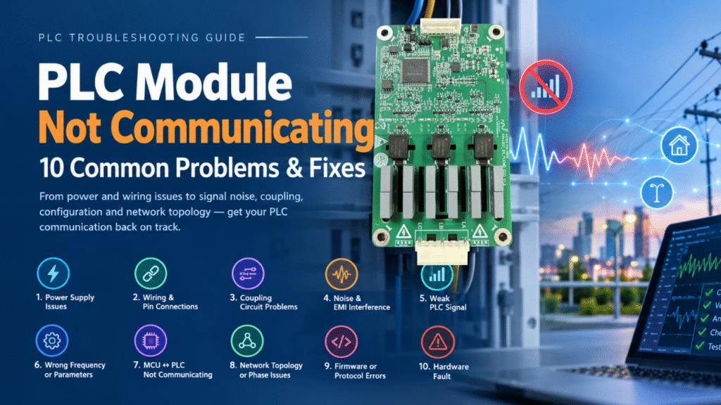
Common Integration Challenges
Although PLC modules simplify development, engineers may still encounter several challenges.
| Challenge | Solution |
|---|---|
| Communication noise | Improve filtering and grounding |
| Signal attenuation | Optimize coupling circuit |
| Poor PCB layout | Follow reference design |
| Address conflicts | Use automatic addressing |
| Firmware synchronization | Implement version management |
| Network congestion | Optimize routing algorithms |
Early validation during development reduces deployment risks.
Best Practices for Successful PLC Integration
To maximize system performance:
- Select modules certified for your target market.
- Follow the reference schematic exactly.
- Keep analog and digital circuits isolated.
- Implement watchdog recovery.
- Support remote firmware upgrades.
- Log communication diagnostics.
- Perform EMC testing early.
- Validate performance under worst-case electrical conditions.
These practices improve reliability and simplify maintenance throughout the product lifecycle.