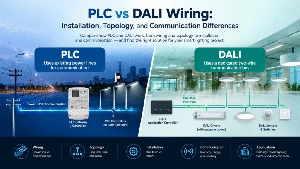
Modern cities and industrial facilities are rapidly adopting smart lighting systems to reduce energy consumption, simplify maintenance, and enable centralized lighting management. One of the most reliable communication technologies for these projects is Power Line Communication (PLC).
Unlike wireless technologies that depend on radio signals, PLC uses the existing electrical power lines to transmit both power and communication data. This significantly reduces installation costs while improving network reliability in environments where wireless communication may be unstable.
This guide explains how to design a PLC smart lighting network, including system architecture, device selection, network topology, installation considerations, and best engineering practices. If you’re new to PLC systems, start with our PLC Smart Lighting System Architecture Guide to understand how all system components work together before designing the network.
What Is a PLC Smart Lighting Network?
A PLC smart lighting network is a communication system where lighting devices exchange data through the existing AC power cables. Learn more about the fundamentals of Power Line Communication technology in our PLC Network Design Guide, which explains how PLC signals travel over existing electrical infrastructure.
The same cable simultaneously delivers:
- Electrical power
- Control commands
- Status information
- Energy monitoring data
- Fault alarms
- Scheduling instructions
Instead of deploying separate communication cables or wireless gateways throughout the project, the power distribution network itself becomes the communication infrastructure.
Typical applications include:
- Smart street lighting
- Tunnel lighting
- Industrial facilities
- Warehouses
- Ports
- Airports
- Stadiums
- Campus lighting
- Commercial buildings
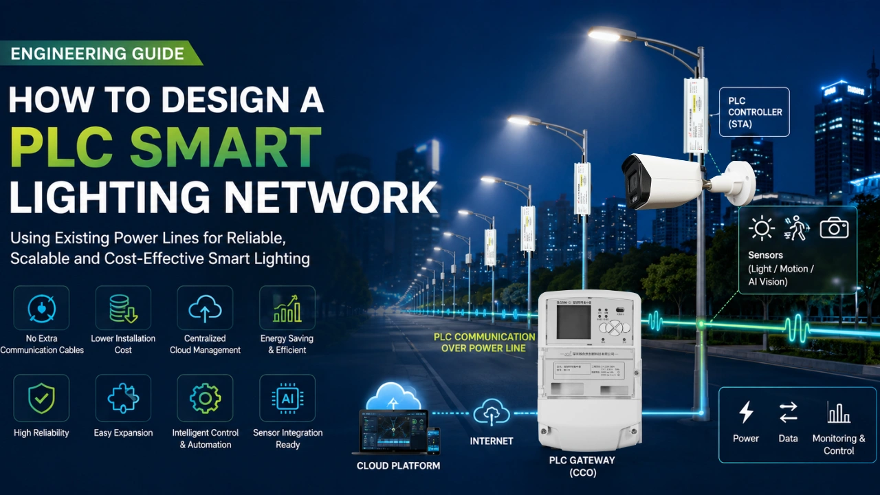
Typical PLC Smart Lighting Architecture
Cloud Management Platform
            │
       Internet / VPN
            │
      PLC Gateway (CCO)
            │
      Power Distribution Cabinet
            │
========================================
 Existing Power Line
========================================
      │        │        │
 PLC Controller PLC Controller PLC Controller
      │        │        │
 LED Driver  LED Driver  LED Driver
      │
 Sensor / Meter / AI Camera
The communication path is straightforward:
Cloud Platform
↓
Gateway
↓
Power Line
↓
PLC Controllers
↓
Lighting Fixtures
Main Components of a PLC Lighting Network
1. Cloud Management Platform
The cloud platform acts as the management center.
Functions include:
- Remote monitoring
- Real-time status
- Fault detection
- Energy reports
- Scheduling
- OTA firmware updates
- User management
- GIS map visualization
2. PLC Gateway (CCO)
The gateway is the master device.
Its responsibilities include:
- Managing PLC communication
- Building the PLC network
- Routing data
- Synchronizing controllers
- Connecting to Ethernet or 4G
- Uploading lighting data to the cloud
Normally one gateway controls an entire lighting distribution cabinet. Explore our PLC Gateway (Concentrator) to see how it manages communication between the cloud platform and hundreds of PLC lighting controllers.
3. PLC Controllers (STA)
Each lighting fixture contains one PLC controller. Our PLC Lighting Controller supports remote switching, dimming, energy monitoring, and fault diagnostics for commercial and municipal lighting projects.
Typical functions include:
- Switching ON/OFF
- 0-10V dimming
- DALI dimming
- Energy metering
- Lamp diagnostics
- Temperature monitoring
- Power monitoring
Each controller communicates with the gateway through the power line.
4. Sensors
Sensors improve automation.
Common examples include:
- Ambient light sensor
- Microwave motion sensor
- AI Vision Sensor
- Energy meter
- Temperature sensor
- Current transformer
Sensor data can trigger automatic lighting adjustments without manual intervention.
Many smart city lighting projects also adopt open interoperability frameworks such as TALQ for integrating lighting infrastructure from different manufacturers.
Selecting the Network Topology
PLC supports several deployment topologies.
Linear Topology
Best for:
- Roads
- Tunnels
- Highways
Advantages
- Simple installation
- Easy troubleshooting
- Stable communication
Tree Topology
Suitable for:
- Industrial parks
- Factories
- Warehouses
Advantages
- Flexible expansion
- Multiple branches
- Good scalability
Mesh Topology
Ideal for:
- Large smart cities
- Campus lighting
- Complex municipal projects
Advantages
- Multiple communication paths
- High redundancy
- Automatic routing
- Better reliability
Modern PLC systems can automatically rebuild routes when one communication path becomes unavailable.
Network Design Steps
Step 1. Divide the Project by Distribution Cabinets
Each electrical distribution cabinet generally contains one PLC gateway.
This minimizes communication distance while simplifying maintenance.
Example:
Cabinet A
↓
80 street lights
↓
Gateway A
Cabinet B
↓
70 street lights
↓
Gateway B
Step 2. Install PLC Controllers
Every luminaire requires its own PLC controller.
Controllers may be integrated into:
- LED drivers
- NEMA receptacles
- Zhaga sockets
- Lighting control modules
Step 3. Plan Communication Distance
Although PLC can communicate over long electrical cables, performance depends on:
- Cable quality
- Electrical noise
- Number of transformers
- Branch circuits
- Signal attenuation
For large projects, install gateways close to the lighting circuits to maintain optimal communication quality.
Step 4. Consider Electrical Noise
Industrial environments often introduce:
- Variable frequency drives
- Motors
- Welders
- Inverters
- High-power equipment
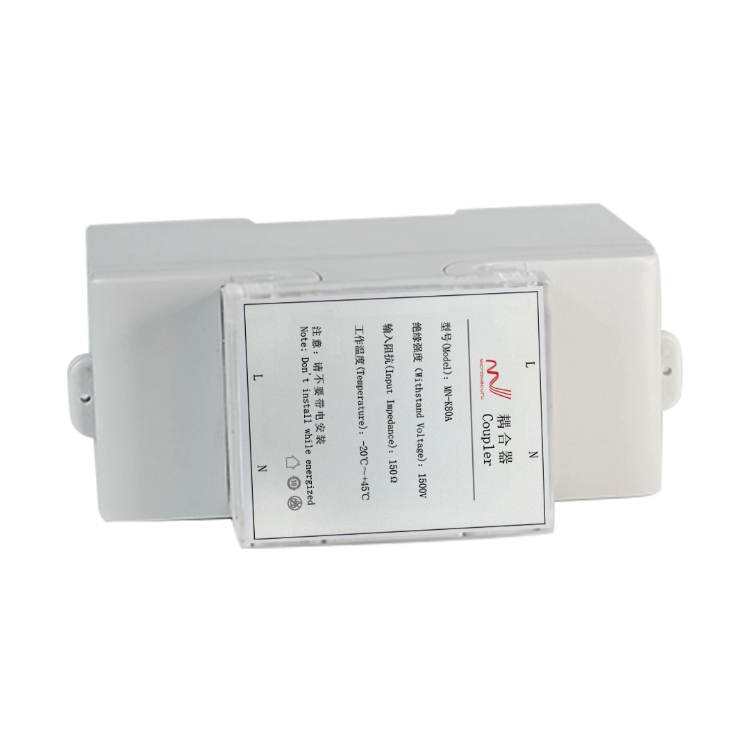
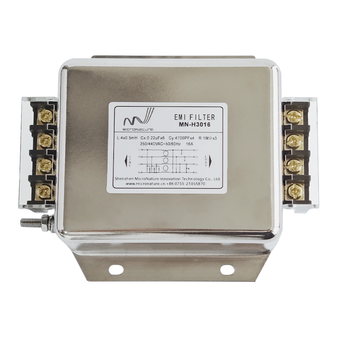
Noise filters or signal couplers may be required to maintain stable communication.
Step 5. Plan Internet Connectivity
The gateway typically connects to the cloud through:
- Ethernet
- Fiber
- 4G LTE
- Cat.1
- 5G
Communication between the gateway and controllers remains entirely on the power line.
Best Practices for PLC Network Design
Successful PLC deployments follow several engineering principles.
Keep one transformer per PLC network
PLC signals generally do not pass efficiently through distribution transformers.
Each transformer should normally have its own gateway.
Avoid unnecessary branch circuits
Excessive branching may reduce communication performance.
Simpler electrical layouts improve signal quality.
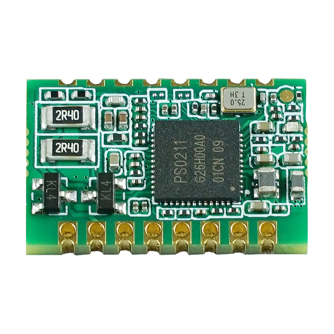
Use industrial-grade PLC modules
Industrial PLC modules provide:
- Better EMC protection
- Stable communication
- Wider operating temperatures
- Long service life
Install surge protection
Outdoor lighting systems should include:
- Surge protection devices
- Lightning protection
- Proper grounding
This protects communication modules from voltage spikes.
Enable Automatic Network Discovery
Modern PLC systems automatically:
- Discover new controllers
- Assign addresses
- Build routing tables
- Monitor communication quality
This greatly reduces commissioning time.
Example Smart Street Lighting Network
A city installs:
- 500 LED street lights
- 5 electrical cabinets
- 5 PLC gateways
- 500 PLC controllers
- AI traffic sensors
- Cloud management platform
The architecture works as follows:
Cloud Platform
↓
Internet
↓
5 PLC Gateways
↓
Existing Power Lines
↓
500 PLC Controllers
↓
LED Street Lights
↓
Sensors
Operators can remotely:
- Dim lights
- Monitor energy
- Detect failures
- Schedule lighting
- Upgrade firmware
- Analyze traffic data
No additional communication cables are required.
Advantages of PLC Network Design
Compared with traditional lighting control systems, PLC offers several advantages:
| Feature | PLC Smart Lighting |
|---|---|
| Additional communication cable | Not required |
| Uses existing power lines | Yes |
| Remote monitoring | Yes |
| Energy management | Yes |
| Automatic networking | Yes |
| High reliability | Yes |
| Low installation cost | Yes |
| Easy expansion | Yes |