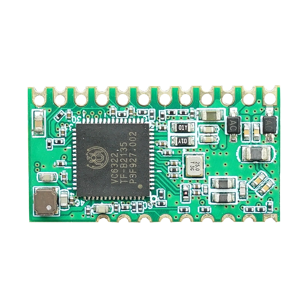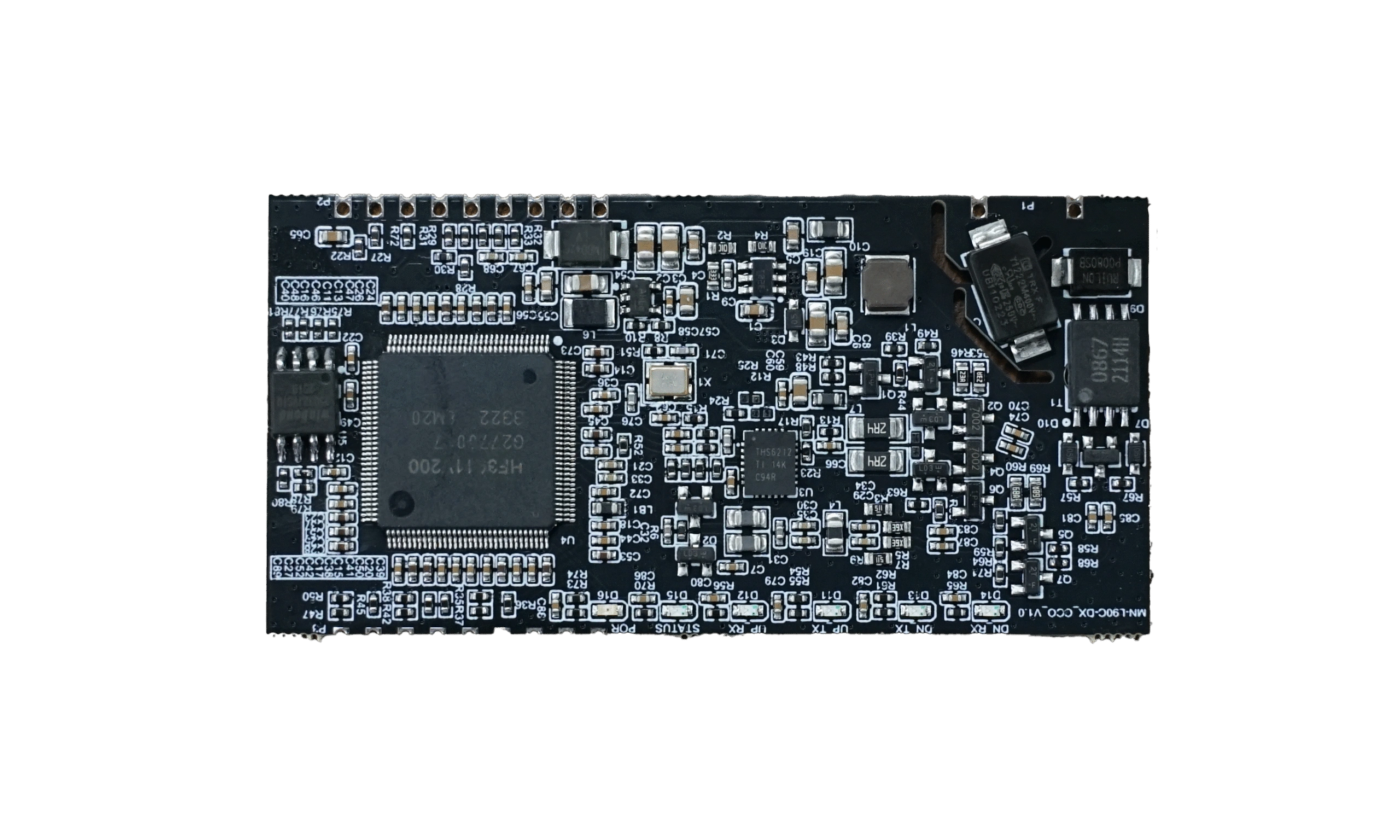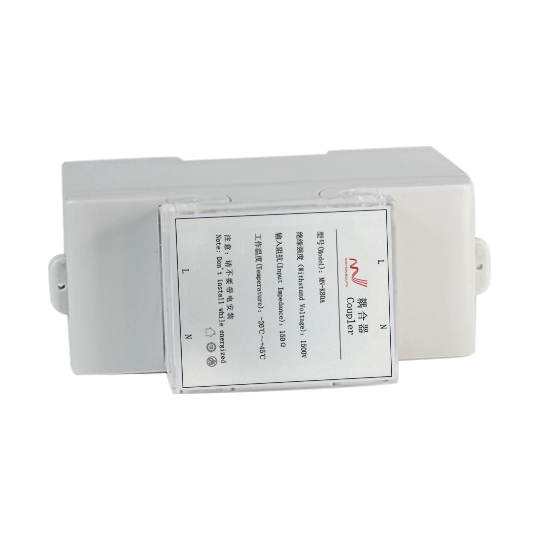
Power Line Communication (PLC) modules enable embedded devices to exchange data over existing electrical power lines. In smart lighting, industrial control, energy management, and other connected electrical products, PLC technology can reduce the need for dedicated communication wiring.
However, integrating a PLC communication module into an OEM product involves more than connecting the module to a power line. Communication failures may originate from the power supply, embedded interface, firmware configuration, coupling circuit, electrical noise, network topology, or application software.
For OEM engineers, identifying the actual cause is essential. Replacing a PLC module without understanding the fault may not solve the problem, especially when the root cause lies in the host controller or the electrical environment.
This guide explains how to troubleshoot PLC communication modules systematically, identify common failure symptoms, and improve communication reliability before mass production.
1. What Is PLC Module Troubleshooting?
PLC module troubleshooting is the process of identifying and resolving faults that prevent a Power Line Communication module from operating correctly or exchanging data reliably over power lines. PLC implementations differ in their supported frequency bands, physical layers, and communication protocols; for systems based on IEEE 1901.1, refer to the official IEEE 1901.1-2018 standard information.
A typical embedded PLC system includes several functional layers:
- Power supply: Provides the operating voltage required by the PLC module and associated circuitry.
- Host controller: Exchanges commands and data with the PLC module through an interface such as UART or another supported interface.
- PLC communication circuitry: Processes and transmits data over the power-line channel.
- Coupling circuit: Connects the communication signal to the power line while providing the required electrical isolation and filtering.
- Communication network: Includes other PLC devices, network coordinators, repeaters where applicable, and the electrical distribution network.
- Application software: Configures devices, manages commands, interprets responses, and reports communication status.
A fault in any of these layers can produce similar symptoms. For example, a device that appears offline may have a power supply problem, an incorrect device address, a host-interface fault, excessive line noise, or an unstable PLC connection.
The most effective troubleshooting strategy is therefore to test each layer separately before investigating the complete system.
2. Common PLC Module Problems and Their Symptoms
The following table summarizes common PLC module faults, their possible causes, and the first checks OEM engineers should perform.
| Symptom | Possible causes | Recommended first check |
|---|---|---|
| PLC module does not start | Incorrect supply voltage, reversed polarity, insufficient current, or damaged hardware | Measure the supply voltage at the module pins |
| Host controller receives no response | Incorrect UART settings, wiring errors, reset problems, or protocol mismatch | Check interface signals and communication settings |
| PLC transmission fails | Incorrect configuration, coupling circuit problems, or electrical noise | Verify the configuration and inspect the PLC signal path |
| Communication works intermittently | Unstable power, variable noise, weak signal margin, or loose connections | Monitor supply stability and repeat tests under different operating conditions |
| Some devices are unreachable | Network topology, addressing errors, excessive attenuation, or insufficient link margin | Test devices individually and compare results across the network |
| Communication becomes unstable when lights turn on | Switching noise from LED drivers or other connected equipment | Compare communication performance with loads switched on and off |
| Data is corrupted or incomplete | Interface timing, protocol framing, buffer handling, or electrical interference | Capture interface traffic and compare transmitted and received data |
| Network commissioning takes too long | Configuration problems, poor link quality, topology limitations, or repeated discovery attempts | Review commissioning logs and test network segments separately |
These symptoms are diagnostic clues rather than definitive proof of a particular fault. Confirm the cause through measurement and controlled testing. For a symptom-by-symptom diagnosis, see our guide to PLC module communication problems.
3. Step 1: Check the PLC Module Power Supply
A stable power supply is the foundation of reliable PLC communication.
If the module cannot start correctly, resets unexpectedly, or loses communication when other circuits activate, investigate the power supply before changing firmware or network settings. Before start, you can first see our article PLC Module Lifecycle: Prototype to Mass Production.
What should OEM engineers check?
3.1 Verify the operating voltage
Measure the voltage directly at the module’s supply pins rather than relying only on the nominal output of the main power supply.
Check that the voltage remains within the module manufacturer’s specified operating range during startup, transmission, reception, and changes in connected loads.
3.2 Check current capability
A supply may provide the correct voltage under light load but experience a voltage drop when the module or its surrounding circuitry becomes active.
Measure the supply under realistic operating conditions and verify that the power source can support the complete circuit.
3.3 Inspect ripple and transient disturbances
Switching power supplies, LED drivers, relays, and other power electronics can introduce disturbances into the local supply.
Use an oscilloscope to observe voltage behavior during startup, switching events, and communication activity. Pay attention to brief dips that a standard multimeter may not capture.
3.4 Check reset and startup behavior
If the module repeatedly restarts, examine the reset circuit, startup sequence, power-on timing, and any external enable signals.
For an embedded PLC design, confirm that the host controller does not begin communicating before the module is ready.
Important: Do not assume that all PLC modules use the same voltage, startup delay, reset behavior, or current requirements. Follow the specific module datasheet and hardware design requirements.
4. Step 2: Troubleshoot the Host Interface
The connection between the PLC module and the host controller is a common source of integration problems.
Many embedded PLC modules support UART or other digital interfaces. The available interfaces, electrical levels, and communication protocols depend on the particular module.
4.1 Verify the physical connections
For a UART connection, check:
- Transmit and receive signal connections.
- Ground reference, where required by the interface design.
- Logic-level compatibility between the host MCU and PLC module.
- Reset, enable, and other required control signals.
- Connector pin assignments against the module datasheet.
Do not connect signals based on connector position alone. Confirm the actual pinout and electrical specifications.
4.2 Confirm UART configuration
Check that the host controller and module use matching communication parameters, including:
- Baud rate.
- Data bits.
- Parity.
- Stop bits.
- Hardware flow control, if supported and required.
For additional guidance on verifying UART and SPI signals, consult this serial interface debugging documentation. Also verify the module’s command protocol, message format, frame length, checksum, and response timing where applicable.
A UART signal that looks electrically correct can still carry invalid commands if the host firmware uses the wrong protocol or framing.
4.3 Capture and analyze the interface traffic
Use a logic analyzer or oscilloscope to inspect communication between the host controller and the PLC module.
A useful test sequence is:
- Send a known valid command.
- Confirm that the signal reaches the module.
- Check whether the module returns the expected response.
- Compare the captured data with the documented protocol.
- Repeat the test with a known-good host or reference design, if available.
If the host sends no command, investigate host firmware and peripheral configuration. If valid commands reach the module but no expected response appears, investigate module readiness, command validity, configuration, and documented response behavior.
If the interface works but PLC communication fails, continue to the PLC channel and network checks.
5. Step 3: Investigate PLC Signal and Coupling Problems
A PLC module communicates through an electrical power network rather than a dedicated data cable. Consequently, the characteristics of the connected power line can directly affect communication performance.
The coupling circuit is particularly important because it provides the interface between the PLC communication circuitry and the power-line channel.
5.1 Inspect the coupling circuit
Check that the coupling circuit matches the module reference design or approved application schematic. For detailed hardware design considerations, see our PLC coupling circuit design guide.
Review:
- Component values and tolerances.
- Inductor, capacitor, transformer, or other coupling components used by the design.
- PCB routing and connection quality.
- Required voltage and surge ratings.
- Isolation and safety requirements for the intended application.
- The integrity of connectors and power-line connections.
Do not change coupling components arbitrarily. The appropriate design depends on the PLC frequency band, modulation method, impedance characteristics, applicable safety requirements, and the module’s electrical interface.
5.2 Check the communication path
Test whether the module can communicate with a known-good peer under controlled conditions.
If communication works in a short test setup but fails in the final product, compare the two setups for differences in coupling, wiring, connected loads, grounding, and electrical noise.
If the problem occurs only after installation, investigate the actual electrical network rather than assuming the module itself is defective.
5.3 Measure signal quality where supported
If the PLC platform exposes signal strength, signal-to-noise ratio, link quality, packet error rate, or retransmission statistics, record these values during testing.
Compare measurements across different loads and network conditions. Such data can help determine whether the issue is associated with weak signal levels, interference, or unstable connectivity.
Not every PLC module exposes the same diagnostic metrics. Use the measurement facilities supported by the relevant hardware and firmware.
6. Step 4: Identify Electrical Noise from Connected Equipment
Electrical noise is an important consideration in PLC-based smart lighting and industrial control systems. Before start your project, choosing a suitable PLC Lighting Solution is neccessary.
LED drivers, switching power supplies, variable-speed drives, relays, and other power electronic devices can affect the electrical environment. The severity depends on the equipment design, switching characteristics, filtering, wiring, and PLC signal band.
How can OEM engineers identify noise-related faults?
Use a controlled comparison:
- Test PLC communication with the target equipment disconnected or in a safe, controlled baseline configuration.
- Record communication success, response time, and available link-quality metrics.
- Connect or activate one electrical load at a time.
- Repeat the measurements under the same network conditions.
- Identify whether a specific load consistently correlates with degraded communication.
For smart lighting products, compare communication performance with LED drivers operating at different power levels, where the design permits safe testing.
If activating a particular load causes a repeatable decline in communication performance, investigate the noise source, filtering, coupling design, and installation arrangement.
Possible engineering improvements
Depending on the verified cause, possible measures include:
- Improving the power supply and filtering design.
- Reviewing the PLC coupling circuit.
- Improving PCB layout and signal-path design.
- Evaluating an appropriate PLC line filter or noise-isolation solution.
- Reviewing the compatibility of connected power electronic equipment.
- Adjusting network architecture or device placement where supported.
Any filtering or isolation solution must be validated against the PLC frequency band and required communication performance. An incorrectly selected filter may attenuate the desired PLC signal as well as unwanted noise.
7. Step 5: Diagnose Network Discovery and Device Communication
A PLC module may operate correctly at the hardware level but fail to join the network or exchange data with the intended coordinator.
This type of fault often appears during system commissioning.
Check the following items
Device configuration: Confirm that the coordinator and end devices use compatible network settings, firmware versions, and communication parameters.
Device addressing: Verify that device identifiers, addressing rules, and network membership are correct for the selected PLC platform.
Commissioning sequence: Check whether the coordinator and end devices follow the required initialization, discovery, and registration sequence.
Network topology: Review the physical electrical connections and supported routing or relay capabilities. Do not assume that all PLC protocols support mesh networking or the same number of relay levels.
Communication distance and attenuation: Evaluate the complete power-line path, including distribution equipment, filters, transformers, and other components that may affect the communication signal.
Network capacity: Check whether the application is generating excessive traffic or sending commands too frequently for the network’s available capacity.
A useful isolation test
Start with a small network containing one coordinator and one known-good end device. Confirm basic communication before adding more devices.
Then expand the network gradually, recording when the failure first appears.
If the basic connection works but the larger network fails, investigate addressing, topology, traffic load, electrical conditions, and configuration differences.
For PLC lighting projects, this method can help distinguish a module-level fault from a problem affecting the complete lighting control network.
8. Step 6: Check Firmware and Software Integration
Hardware measurements alone may not reveal problems caused by embedded software.
The host MCU, PLC module firmware, and application software must exchange data according to the correct interface and protocol specifications.
Common firmware-related issues
- The host sends commands before the PLC module is initialized.
- Firmware uses an incorrect command sequence or configuration.
- Receive buffers are too small for the expected message size.
- UART interrupts or DMA handling cause data loss.
- The software fails to handle timeouts, retries, or incomplete frames.
- Multiple tasks access the interface without appropriate synchronization.
- Firmware assumes that a command has succeeded without checking the response.
- The host and module use incompatible protocol or firmware versions.
Recommended debugging procedure
First, log the commands sent by the host and the responses received from the module.
Next, check timestamps, message lengths, error codes, and timeout events. If the module provides diagnostic logs, compare them with the host-side records.
Finally, test error handling by introducing controlled communication interruptions and confirming that the host can detect failures and recover according to the design requirements.
For OEM products, reliable error reporting is particularly important. A controller should distinguish between a device that is temporarily unreachable and one that has failed permanently, whenever the available diagnostic information allows that distinction.
9. Step 7: Troubleshoot Intermittent PLC Communication
Intermittent failures are often more difficult to diagnose than complete communication failures because the system may work correctly during a short laboratory test.
Possible causes include unstable supply voltage, variable electrical noise, marginal signal quality, loose connections, temperature-related component behavior, or software timing problems.
How to reproduce intermittent faults
Extend the test duration. Run repeated communication cycles over a representative operating period rather than relying on a single successful connection.
Vary the electrical load. Test under the expected operating conditions of the complete product.
Record communication statistics. Where available, log successful transmissions, failed transmissions, retries, timeouts, reconnects, and signal-quality indicators.
Check environmental conditions. Evaluate operation across the intended temperature and supply-voltage ranges, following the product and component specifications.
Inspect physical connections. Check connectors, solder joints, PCB assemblies, and wiring for defects that may appear only under vibration, heating, or repeated operation.
Compare against a reference setup. Use the same module and firmware in a known-good configuration to help isolate whether the problem follows the module, the host product, or the electrical network.
A repeatable test with recorded measurements is generally more useful than making several hardware or firmware changes simultaneously.
10. Step 8: Build a Repeatable PLC Module Test Procedure
OEM engineers should establish a standard troubleshooting and verification process before moving from prototype to mass production.
A practical test procedure can include the following stages.
Stage 1: Visual and electrical inspection
- Verify component orientation and module connections.
- Confirm supply voltage and current requirements.
- Check reset, enable, and host-interface signals.
- Inspect the coupling circuit and relevant PCB layout.
Stage 2: Host-interface verification
- Send documented test commands.
- Verify responses using a logic analyzer or equivalent tool.
- Confirm protocol settings and error handling.
- Record the module and firmware versions.
Stage 3: Basic PLC communication
- Connect the device to a known-good PLC peer or coordinator.
- Verify network initialization and device registration.
- Exchange repeated test messages.
- Record communication failures and response times.
Stage 4: System integration testing
- Integrate the PLC module into the complete OEM product.
- Test with representative power supplies, loads, and wiring.
- Evaluate performance under expected operating conditions.
- Investigate any degradation relative to the reference setup.
Stage 5: Reliability and regression testing
- Repeat tests after firmware or hardware revisions.
- Verify recovery from temporary communication interruptions.
- Check behavior across the required environmental and supply ranges.
- Document test results, known limitations, and corrective actions.
The acceptance criteria should be defined before testing. Set appropriate targets for communication success rate, response time, network recovery, and operating conditions based on the intended application and system requirements.
11. When Should OEM Engineers Suspect a Defective PLC Module?
Not every PLC communication problem indicates a defective module.
Before requesting a replacement, confirm that:
- The supply voltage and electrical connections comply with the specifications.
- The host interface is configured correctly.
- The required initialization and communication sequences are followed.
- The coupling circuit is correctly implemented.
- The test setup provides a suitable PLC communication path.
- Electrical noise and network configuration have been investigated.
- The module has been tested in a known-good reference setup, where possible.
A hardware defect becomes more likely when the same failure consistently follows the module across multiple verified test setups, while the supply, interface, configuration, and communication environment are confirmed to be correct.
Record the module identification, hardware revision, firmware version, supply conditions, test configuration, error logs, and measurement results before escalating the issue.
This information helps the engineering team distinguish a genuine hardware fault from an integration or application problem.
12. How to Reduce PLC Troubleshooting During OEM Product Development
The best troubleshooting strategy is to prevent common integration problems before the design enters production. How to Choose a Power Line Communication Module for OEM Products this article will help you understand better.
OEM engineers can reduce development risk by following these practices:
- Select the module early. Confirm the supported PLC protocol, electrical requirements, interfaces, and target application before finalizing the host PCB.
- Follow the reference design. Use the manufacturer’s documented circuit and layout recommendations as the starting point.
- Validate the host interface independently. Confirm command exchange before debugging the complete PLC network.
- Test with representative loads. Include the actual power electronics and electrical environment in system validation.
- Implement diagnostic logging. Record communication errors, timeouts, retries, and available link-quality data.
- Maintain hardware and firmware version control. Record the versions used for each successful test configuration.
- Test early and repeatedly. Identify integration problems during prototyping instead of waiting for final product verification.
- Work with the module supplier. Clarify interface requirements, reference designs, supported features, and application-specific constraints.
For products such as smart streetlights, tunnel lights, industrial luminaires, and energy-management controllers, the electrical environment can vary significantly between installations. Testing only on a development bench is therefore insufficient to establish system-level reliability. Before finalizing a new product design, review our PLC module design checklist for OEM development.
13. How MicroNature Supports PLC Module Integration for OEM Products
MicroNature develops Power Line Communication solutions for smart lighting and industrial applications, including embedded PLC communication modules and related system devices.
For OEM engineers, module selection should consider the host interface, supported PLC technology, electrical integration requirements, firmware compatibility, and intended application.
MicroNature’s PLC module portfolio includes the MN-L60C, MN-L80A, and MN-L80C families, with features and interface options depending on the model.
When evaluating a PLC module for an OEM design, engineers should confirm:
- Supported communication technology and protocol.
- Available host interfaces and electrical requirements.
- Reference circuits and coupling requirements.
- Firmware and configuration compatibility.
- Network architecture and intended application.
- Technical support and customization requirements.
For smart lighting projects, PLC technology can enable communication between controllers and luminaires over existing power lines, potentially reducing the need for dedicated communication wiring.
MicroNature also provides PLC-based lighting control solutions and supports hardware and software customization for application-specific projects.
If your team is integrating PLC communication into a new controller, luminaire, or industrial electrical product, contact MicroNature to discuss module selection, interface compatibility, and system integration requirements.