An industrial LED dimmable driver is a critical component in modern smart lighting systems, enabling precise brightness control, energy management, and integration with industrial lighting control platforms. In PLC-based smart lighting systems, the dimmable LED driver works together with PLC controllers, gateways, sensors, and cloud platforms to provide reliable lighting automation for warehouses, factories, tunnels, power plants, and municipal projects.
An industrial lighting upgrade can look straightforward on a drawing and become expensive the moment commissioning begins. A driver dims unevenly. A controller cannot reach several luminaires. A fixture flickers at low output. New communication cables require shutdowns, lifts, conduit work, and another round of testing. By then, the original wattage calculation no longer feels like the most important decision.
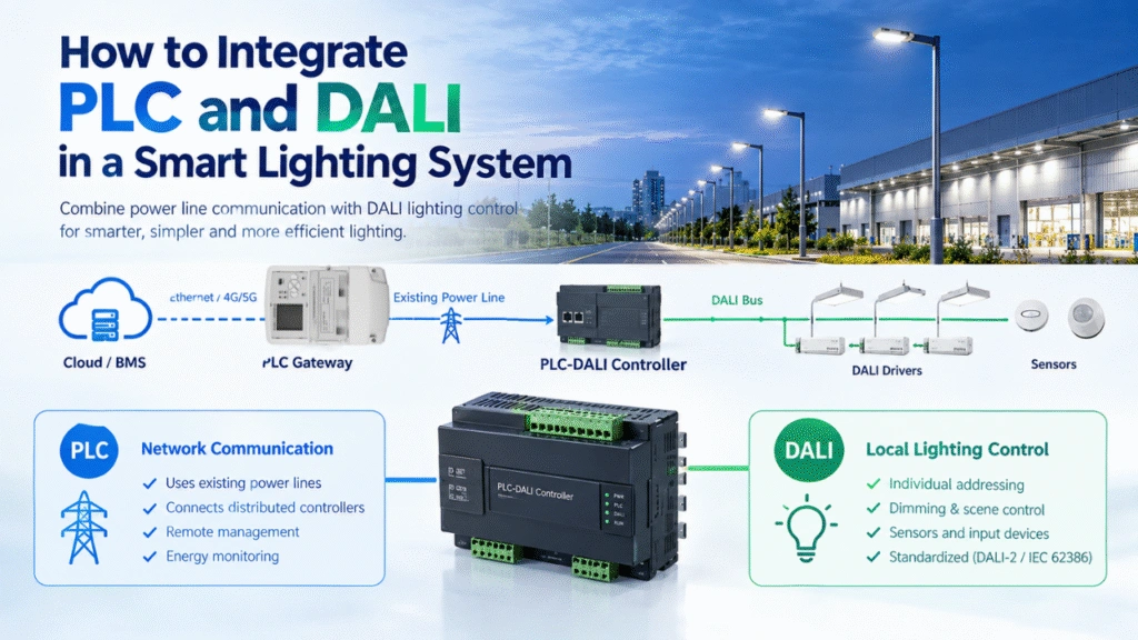
The real question is whether the driver, LED load, dimming interface, electrical circuit, field controller, gateway, and management platform can operate as one system. An industrial LED dimmable driver handles only part of that job. It powers the LED fixture and responds to a compatible dimming input. Power Line Communication carries commands and operating data through the electrical network, while a local controller converts the requested lighting level into the signal the driver can use.
This distinction matters in warehouses, factories, shipyards, power plants, tunnels, highways, and municipal lighting networks. These environments often contain long circuits, physical barriers, switching equipment, motors, frequency converters, transformers, and other sources of electrical noise. A reliable design must account for the site rather than assume that one product specification will solve every integration problem.
MicroNature develops PLC lighting hardware and software for industrial and municipal projects. Its supplied company profile reports more than ten years of focus on PLC technology, service coverage in more than 30 countries, over 20 company patents, internal research and development resources, and a five-year warranty program. Buyers should still confirm which warranty, certification, customization, and support terms apply to the product and project under review.
For fixture-level dimming options, review the PLC Led Dimmable Driver range and discuss the LED module, circuit design, environmental conditions, and control objectives before selecting a model.
What an Industrial LED Dimmable Driver Actually Does
An industrial LED dimmable driver converts incoming electrical power into the controlled voltage or current required by an LED module. It also accepts a compatible dimming command, such as a 0–10V signal, and adjusts its output so the fixture produces the requested light level. Industrial projects must also verify thermal performance, power quality, surge conditions, electromagnetic compatibility, load matching, protection requirements, and controller integration.
The word “industrial” should mean more than a rugged-looking enclosure. A driver installed above a warehouse aisle faces different conditions from one mounted inside a tunnel cabinet or near heavy electrical equipment. Ambient temperature, enclosure ventilation, cable length, switching frequency, line disturbance, installation access, and operating hours all affect the final design.
The driver’s first responsibility is stable power conversion. Depending on the LED module, the project may require a constant-current or constant-voltage design. The output window must suit the actual LED load, not just the fixture’s marketing wattage. Engineers also need enough operating margin to avoid pushing the driver continuously at an unsuitable limit.
Dimming adds another compatibility layer. A nominally compatible 0–10V interface can still behave differently at the bottom of the dimming range. The fixture may not switch fully off. Its brightness curve may feel abrupt. Two driver models may produce different perceived light levels from the same control voltage. That is why buyers should request a documented dimming curve, minimum output information, control-wire requirements, and a sample test with the intended controller.
For projects that require an AC driver configuration, the PLC AC Led Dimmable Driver page provides a starting point for technical discussion. Final approval should rely on the applicable datasheet, wiring diagram, load test, and project-specific compatibility confirmation.
The Driver and the Lighting Controller Have Different Jobs
A driver regulates electrical power for the LED module. A lighting controller decides or receives the requested operating state. In a PLC smart lighting architecture, the controller listens for commands carried over the power line and then provides the fixture-level control output required by the driver.
That separation gives system designers more flexibility, but it also creates an integration boundary. The controller output must match the driver input. The driver must react consistently across the required dimming range. The circuit must allow reliable PLC communication. The gateway and software platform must address the correct field devices. Treating any one of these components as an isolated purchase increases commissioning risk.
Reliable dimming comes from the complete architecture, not from the driver alone.
PLC Means Power Line Communication in This Lighting System
PLC has two common technical meanings. In this article, PLC means Power Line Communication: a method that carries communication signals over electrical conductors that already deliver power. It does not mean the programmable logic controller commonly used for machine automation, process control, or production equipment.
The two technologies can appear within the same industrial facility, which makes precise language important. A factory may use programmable logic controllers for conveyors or production lines while using Power Line Communication for lighting control. Writing the full term during design reviews, specifications, and tender documents prevents confusion between the automation platform and the lighting communication network.
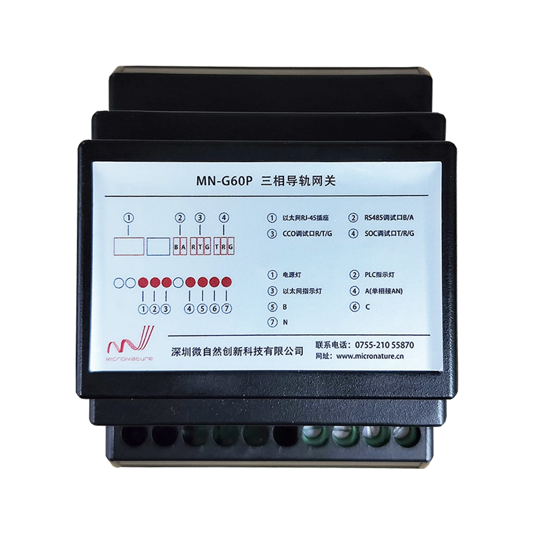
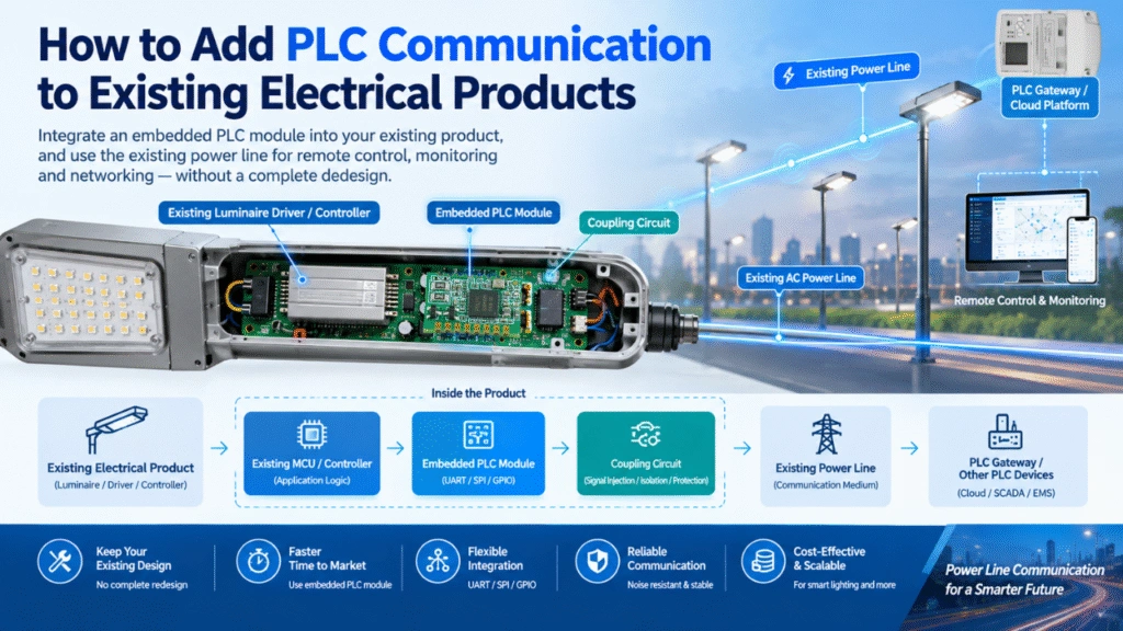
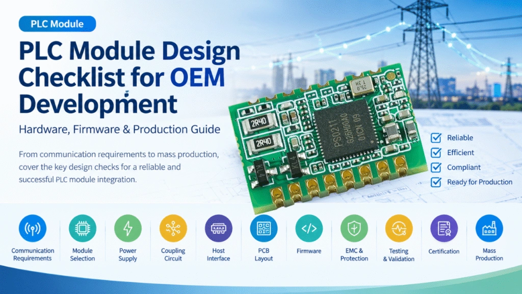
At the hardware level, a power line communication module allows equipment manufacturers and system integrators to add PLC communication functions to controllers, luminaires, gateways, and other connected devices. Module selection should consider the required frequency category, communication rate, topology, network capacity, electrical environment, and integration interface.
0–10V Provides the Dimming Interface
In the featured architecture, PLC carries commands and monitoring data. It does not act as the driver’s dimming signal. The PLC field controller receives a command from the network and produces the 0–10V control level that the dimmable LED driver accepts.
This system should not be described as a built-in DALI driver solution. DALI uses a dedicated digital lighting-control bus and requires compatible devices, addressing, and bus planning. The MicroNature driver information supplied for this article identifies 0–10V as the dimming interface. Projects designed around DALI should therefore evaluate a different driver and control architecture rather than assume direct compatibility.
How PLC Smart Lighting Executes a Dimming Command
Imagine a logistics center at the beginning of a night shift. Several loading aisles need full output. Reserve storage areas can remain at a lower level. A motion sensor detects activity near a picking zone, while the facility manager has already scheduled reduced lighting in an unoccupied section.
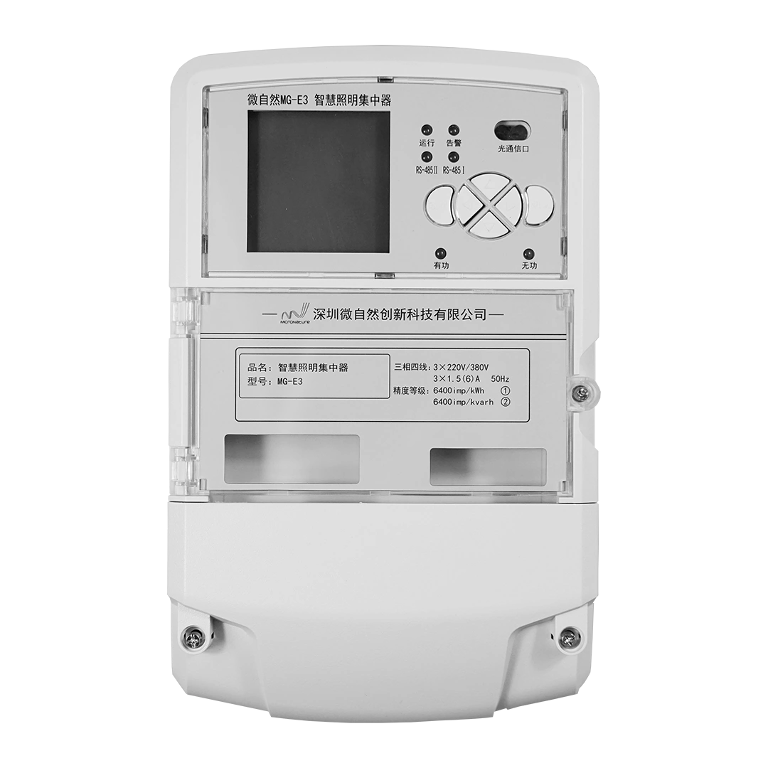
The command may begin in a cloud platform, mobile application, central management system, preset schedule, or connected sensor. A gateway or central controller sends the instruction into the power-line communication network. The signal travels through the relevant electrical circuit to the assigned field controller. That controller interprets the command and sends a corresponding 0–10V level to the driver. The driver then adjusts the regulated power supplied to the LED fixture.
Readers who need a broader view of the controller, gateway, communication module, sensor, platform, and field-device relationship can review the PLC Smart Lighting System Architecture Guide.
The operating sequence normally follows five practical steps:
- A user, schedule, sensor, or connected platform generates a lighting command.
- The gateway or central controller injects the command into the relevant power-line network.
- The assigned PLC field controller receives and processes the instruction.
- The controller sends the required 0–10V output to the dimmable LED driver.
- The driver regulates the LED load to produce the requested light level.
This architecture can reduce the need for separate communication cabling because it uses existing electrical conductors as the communication medium. The exact reduction depends on circuit topology, cabinet design, signal coverage, phase arrangement, isolation requirements, and the condition of the existing installation. Engineers should never treat “no extra communication wiring” as permission to skip a site survey.
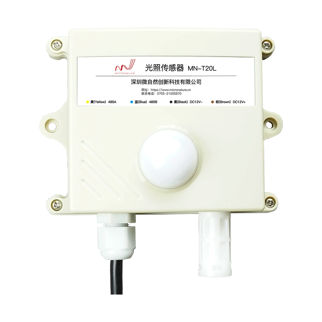
PLC also avoids complete dependence on wireless coverage. That can help in facilities with metal structures, enclosed areas, long corridors, or distributed lighting circuits. It does not make the network immune to interference. Motors, variable-frequency drives, switching power supplies, transformers, capacitor banks, and other electrical equipment can influence signal conditions. A professional design may require circuit mapping, noise testing, phase planning, filters, or signal isolators.
At the field level, a project may use a PLC Led Dimmable Switch when the required architecture calls for remote switching and dimming. Other circuits may suit a PLC Light Dimmer Switch, while installations that need coordinated control of two outputs can evaluate the PLC Dual Light Controller. The correct choice depends on load type, output requirements, cabinet layout, control logic, and the confirmed product specification.
The Specifications That Prevent Expensive Mismatches
Procurement teams often begin with driver wattage because it offers an easy comparison. Wattage alone cannot confirm compatibility. A useful approval process starts with the LED module and works backward through the driver, controller, electrical circuit, and management system.
Start with the LED Load
Confirm whether the fixture requires constant-current or constant-voltage power. Record the LED module’s operating voltage, rated current, maximum power, series or parallel arrangement, thermal conditions, and allowable tolerances. The driver’s output window must cover the actual load throughout normal operation.
A mismatch can cause failure to start, unstable output, overheating, reduced dimming range, or premature component stress. Engineers should also check how temperature changes affect the LED module and driver. A system that works on a bench may behave differently inside a sealed luminaire near the roof of a warehouse.
Check Input Power and Power Quality
Verify the input-voltage range, line frequency, efficiency, power factor, total harmonic distortion, inrush current, isolation design, and protective functions. For projects with many fixtures on one circuit, inrush current can influence breaker selection and switching design even when the steady-state load appears acceptable.
Power factor and harmonic performance also matter at system scale. The buyer should request test values for the exact model and operating condition under consideration rather than rely on a broad product-family statement.
Examine the Entire 0–10V Dimming Range
Ask how the driver behaves from maximum output down to its documented minimum. Confirm whether the interface sinks or sources current as required by the controller. Check polarity, control-wire routing, response time, off-state behavior, and the effect of an open or shorted control circuit.
Low-level performance deserves a physical test. A driver may produce smooth results from full output to 20 percent and then step abruptly, flicker, or switch off below that point. Human perception also follows a nonlinear response, so an electrically linear curve may not look visually linear.
Match the Environment, Not Just the Enclosure
Review operating and storage temperature, humidity, ventilation, installation position, ingress protection where relevant, surge exposure, vibration, electromagnetic compatibility, cable routing, and maintenance access. An outdoor cabinet, a high-bay luminaire, and an indoor electrical room impose different requirements.
Do not publish or approve an IP rating, surge value, service-life estimate, or operating-temperature range without the datasheet or applicable test report. Similar-looking products can carry different ratings, and an enclosure may change the final protection level of the assembled fixture.
Use Evidence to Close the Approval Gap
| Requirement | Why It Matters | Evidence to Request |
|---|---|---|
| Output current and voltage | Confirms that the driver matches the LED module | Model datasheet, load calculation, and sample test |
| 0–10V dimming behavior | Determines minimum output, response, and visual consistency | Dimming curve, controller compatibility statement, and low-level test |
| Power factor and harmonics | Affects circuit performance when many fixtures operate together | Test data for the applicable input and load condition |
| Inrush current | Influences breaker, relay, and circuit design | Measured peak, duration, and recommended fixture quantity per circuit |
| Surge and EMC performance | Supports operation in electrically demanding environments | Relevant test reports and installation guidance |
| Thermal performance | Helps prevent overheating inside the final luminaire or cabinet | Temperature limits, case-temperature guidance, and thermal test conditions |
| PLC controller integration | Reduces wiring and commissioning errors | System diagram, terminal definition, and compatibility confirmation |
| Warranty and support | Clarifies responsibility after delivery | Written warranty terms, exclusions, and support procedure |
Where Controlled Dimming Solves Real Operating Problems
Warehouses and Logistics Centers
High-bay lighting combines large fixture quantities, long operating hours, changing occupancy, and difficult maintenance access. A well-designed control system can assign schedules by zone, raise output when workers or vehicles enter an area, and reduce output in inactive aisles.
The driver must respond consistently across many fixtures. Small differences become visible when a long aisle contains dozens of luminaires. Pilot testing should therefore include several fixtures, the intended control cable arrangement, representative mounting conditions, and the actual PLC controller.
Factories, Shipyards, and Heavy Industrial Sites
Industrial buildings often contain cranes, machinery, steel structures, distribution cabinets, motors, and long branch circuits. These features can complicate both wireless coverage and power-line communication. PLC offers a practical route when the electrical network provides a suitable communication path, but the designer must study circuit boundaries and noise sources.
Maintenance teams also need understandable documentation. A technically capable system loses value when no one can identify device addresses, circuit assignments, gateway settings, or alarm meanings six months after handover. The commissioning package should include drawings, configuration records, test results, and fault-handling procedures.
Power Plants and High-EMI Environments
Power plants can contain strong electromagnetic interference, high-power switching equipment, transformers, and complex phase arrangements. The driver alone cannot make the communication network resilient. Engineers must consider the entire topology, including controller locations, phase coupling, electrical noise, cabinet design, grounding, and possible signal isolation.
Single-phase or three-phase signal isolators may help manage communication boundaries or suppress unwanted high-frequency interference in suitable designs. Their use should follow a site assessment and verified wiring plan rather than a generic rule.
Tunnels, Highways, and Municipal Lighting
Long linear infrastructure creates a different maintenance problem. A failed fixture may sit far from the control room, and physical inspection can require lane closures, specialized vehicles, or restricted access windows. Remote lamp-status information and fault alerts can help teams prioritize inspections, although the available data depends on the installed controller, gateway, and platform.
Scheduled dimming can also support operating strategies that change by time, zone, traffic condition, or project requirement. Any claim about energy savings should come from the actual baseline load, operating hours, dimming schedule, and measured results.
PLC, LoRa, Cat.1, and DALI Serve Different Design Priorities
Technology comparisons become misleading when they treat every option as a direct substitute. PLC, LoRa, and Cat.1 mainly describe communication approaches. DALI describes a digital lighting-control bus. A 0–10V driver describes the fixture-level dimming interface. These layers can solve different parts of the system.
Power Line Communication uses electrical conductors as the communication medium. It can reduce separate control wiring and work well in industrial retrofits, tunnels, roads, warehouses, and distributed municipal circuits when the power-line environment supports the design. It requires circuit and noise assessment.
LoRa uses wireless radio communication. It can serve sites where designers can establish suitable coverage, antenna placement, network capacity, and interference conditions. Buildings with heavy metal structures, deep indoor areas, or difficult radio paths may require additional planning.
Cat.1 uses a cellular network. It can suit dispersed outdoor assets or independent controllers that need direct remote communication. The design must consider cellular coverage, service availability, data costs, device management, and cybersecurity responsibilities.
DALI uses a dedicated wired lighting-control bus and compatible digital devices. It often fits projects designed around DALI addressing and commissioning from the beginning. It should not be presented as an included feature of a 0–10V MicroNature driver unless the exact product documentation confirms it.
PLC itself also includes narrowband, mid-band, and broadband approaches. These categories differ in frequency, communication rate, network behavior, range, node capacity, and interference-management methods. Buyers should compare product-specific values and test evidence rather than assume that a broader frequency category automatically performs better in every lighting project.
KNX and DMX do not provide a useful central comparison for the industrial, highway, tunnel, power-plant, and municipal applications discussed here. They address different control ecosystems and project priorities, so adding them would distract from the systems that buyers commonly evaluate for these environments.
Calculate Project Value from the Actual Site
A credible business case should show where costs change and which assumptions drive the result. Start with fixture quantity, connected wattage, annual operating hours, present switching pattern, expected dimming schedule, electricity rate, communication-cable requirements, installation labor, commissioning time, and maintenance activity.
Calculate energy use for the existing condition, then calculate it again for each proposed operating state. For example, separate occupied hours at full output, standby hours at a reduced level, and scheduled off periods. Use measured driver input power at those operating levels when available. Do not treat a 50 percent light command as proof of exactly 50 percent electrical consumption.
Next, compare infrastructure costs. PLC may reduce communication-cable installation, but the project may still require gateways, controllers, isolators, cabinet modifications, commissioning labor, and software integration. Include those items rather than presenting reduced cabling as a cost-free upgrade.
Maintenance value may come from remote status checks, fault alerts, easier device grouping, and faster problem localization. Use the term predictive maintenance only when the platform collects enough operating data and includes a documented analytics function that can predict a likely failure. Otherwise, describe the narrower functions the system can verify.
How to Evaluate an Industrial LED Dimmable Driver Supplier
A polished catalogue cannot replace engineering evidence. Procurement teams may search for an OEM industrial LED dimmable driver manufacturer or an ODM industrial LED dimmable driver supplier, but those labels do not confirm competence by themselves. The supplier should understand the driver, the PLC communication layer, the controller output, the electrical circuit, and the management platform.
Ask the supplier to review the LED load, input power, dimming behavior, operating temperature, enclosure, cable arrangement, surge environment, circuit topology, controller model, and required monitoring functions. A useful response should identify missing information and design risks rather than rush directly to a quotation.
A customized dimmable LED driver provider should define what “customized” includes. The scope may cover electrical parameters, housing, firmware, software functions, controller logic, branding, packaging, documentation, or system integration. Each item has different engineering, validation, tooling, order-quantity, and delivery implications.
MicroNature’s client information states that its internal team supports hardware and software customization. It also clarifies that gateway hardware does not normally require routine customization; instead, system integrators can generally use open APIs or SDKs to connect project-specific functions. Buyers should confirm interface documentation, development support, software ownership, update responsibilities, and acceptance criteria before development begins.
A high quality industrial LED dimmable driver factory should support that description with traceable quality-control procedures, model-specific test documents, warranty terms, production records, and relevant project references. Similarly, an industrial LED dimmable driver company should explain how it handles design review, samples, compatibility testing, engineering changes, production inspection, field troubleshooting, and warranty claims.
For industrial LED dimmable driver manufacture and customization, request at least the following evidence: a complete datasheet, wiring diagram, dimming curve, compatibility statement, thermal guidance, EMC and surge information, relevant compliance documents, sample-testing plan, production quality process, warranty terms, and a named technical-support route.
Why Choose MicroNature for Industrial PLC LED Dimmable Driver Solutions
MicroNature provides industrial LED dimmable driver and PLC lighting control solutions designed for large-scale lighting applications. Unlike traditional lighting suppliers that only provide LED drivers, MicroNature focuses on complete PLC-IoT lighting architecture, including PLC communication modules, controllers, gateways, sensors, cloud platforms, and software integration.
This integrated approach allows EPC contractors and lighting manufacturers to design scalable smart lighting systems for warehouses, factories, tunnels, highways, ports, and municipal projects.
Because the driver forms only one part of the control chain, MicroNature can help project teams evaluate how the dimming interface, PLC field controller, communication module, gateway, sensor strategy, and software platform work together. This system-level perspective can reduce the risk of selecting individually capable components that fail to integrate during commissioning.
Lighting manufacturers can use MicroNature’s power line communication modules to add PLC connectivity to compatible fixtures or controllers. EPC contractors and system integrators can also use the PLC Smart Lighting System Architecture Guide when planning device layers, communication paths, management functions, and project responsibilities.
Project-specific support should begin with technical data rather than a generic product request. Fixture parameters, circuit drawings, environmental conditions, dimming objectives, network size, sensor requirements, platform integration needs, and commissioning expectations help the engineering team recommend a more suitable architecture.
Commission the Network Before Scaling the Installation
A pilot circuit catches problems while they remain manageable. It should reproduce the intended fixture, driver, controller, cable length, circuit condition, gateway, software platform, and environmental influences as closely as practical.
Begin by recording the LED module voltage, current, wattage, and driver type. Confirm the required minimum light level and switch-off behavior. Map the phases, branch circuits, distribution panels, transformers, and controller locations. Identify large motors, variable-frequency drives, switching equipment, and other likely noise sources.
Install a representative group of fixtures and test full output, intermediate levels, minimum output, switching, schedule execution, device addressing, status reporting, and fault behavior. Repeat tests during realistic facility operation, because electrical conditions can change when heavy equipment starts or production shifts begin.
Record controller addresses, circuit assignments, gateway settings, dimming values, alarm rules, firmware versions, and acceptance results. Give the maintenance team a current wiring diagram and a practical troubleshooting sequence. A good handover should help a technician distinguish among a failed driver, LED module problem, controller issue, communication interruption, gateway fault, and configuration error.
Prepare the Project Data That Leads to a Useful Recommendation
The fastest route to a workable solution is a complete project brief. Record the fixture quantity, LED module voltage and current, driver wattage, input power, circuit diagram, phase arrangement, cable distances, distribution-panel layout, installation environment, operating temperature, known interference sources, required dimming range, schedule logic, sensor strategy, remote-management requirements, alarm expectations, and project timeline.
Also explain what problem the project must solve. A warehouse may need occupancy-based aisle control. A tunnel may prioritize long circuit coverage and remote fault information. A power plant may need careful communication planning around strong electrical interference. A municipal project may need centralized scheduling across distributed lighting assets.
Send these details to MicroNature for a driver-controller review, proposed system architecture, wiring guidance, sample plan, and quotation.
Company-specific experience, patent, service-coverage, customization, and warranty statements in this article come from MicroNature’s supplied company profile. Product ratings and project outcomes should be confirmed through the applicable datasheets, test documents, contracts, and verified case records before publication or procurement.