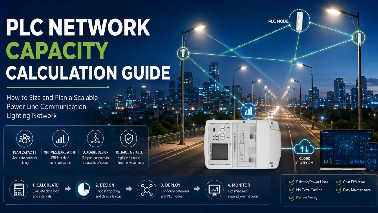
As smart cities continue to adopt intelligent lighting systems, Power Line Communication (PLC) has become one of the most reliable communication technologies for street lighting, industrial facilities, ports, warehouses, campuses, and tunnel lighting.
One of the most common questions engineers ask is:
“How many lighting nodes can one PLC network support?”
The answer depends on more than simply counting luminaires. A properly designed PLC network considers bandwidth, communication intervals, response time, electrical topology, and future expansion. There is no universal maximum number of lights that one PLC gateway can control. The practical limit depends on the PLC communication technology, electrical topology, traffic volume, reporting interval, interference, and required response time. For this reason, MicroNature recommends calculating network capacity based on communication load and then validating the design under actual electrical conditions.
This guide explains how to calculate PLC network capacity and design a scalable PLC lighting system. For more reference, can see IEEE standard.
What Is PLC Network Capacity?
PLC network capacity refers to the maximum number of devices that can communicate efficiently through one PLC network while maintaining acceptable communication speed and reliability.
A typical PLC lighting network includes:
- PLC Gateway or Concentrator
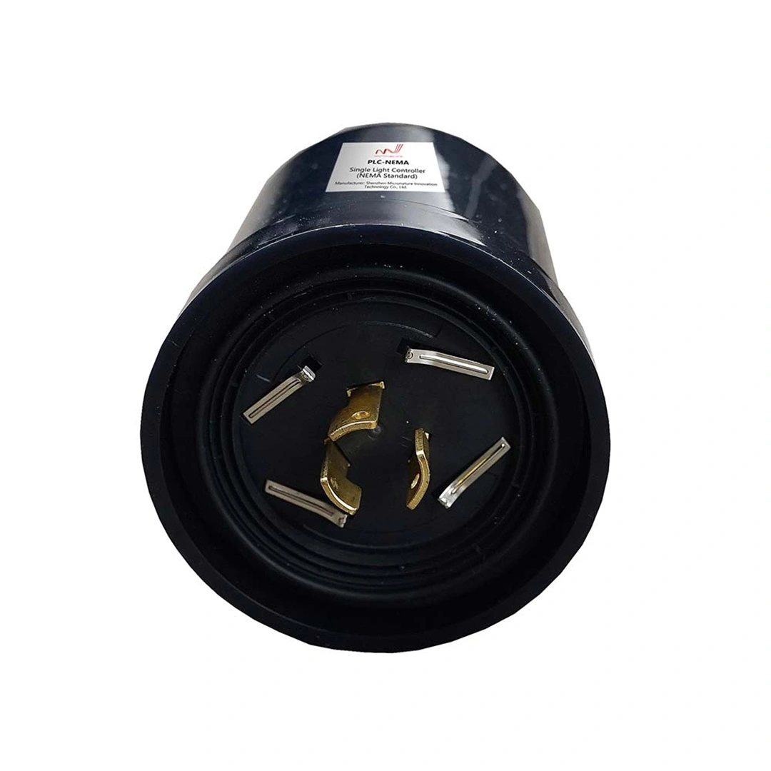
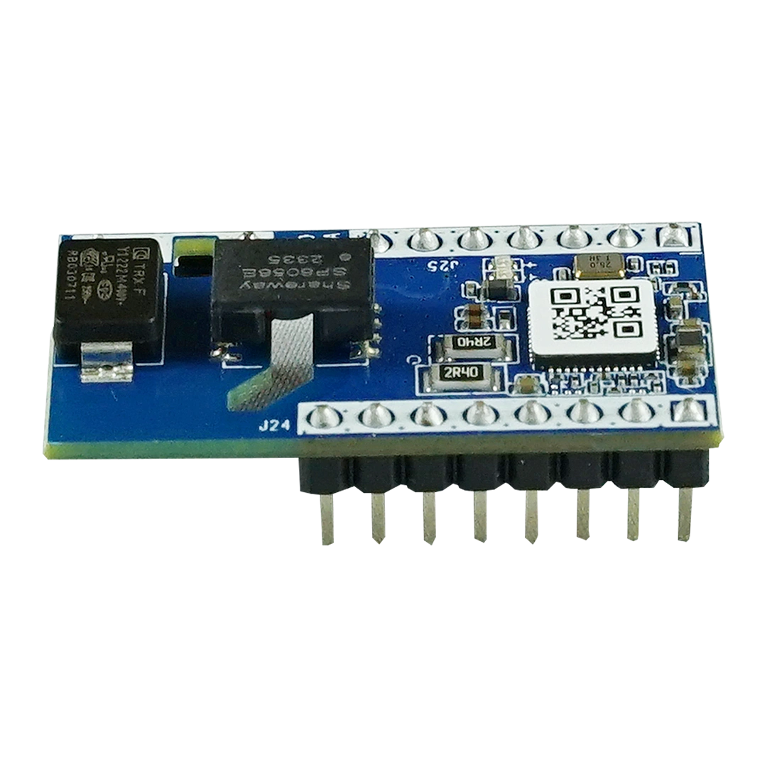
- PLC Controllers
- PLC Dimmable LED Drivers
- AI Sensors
- Light Sensors
- Environmental Sensors
- Electrical Cabinets
- Cloud Platform
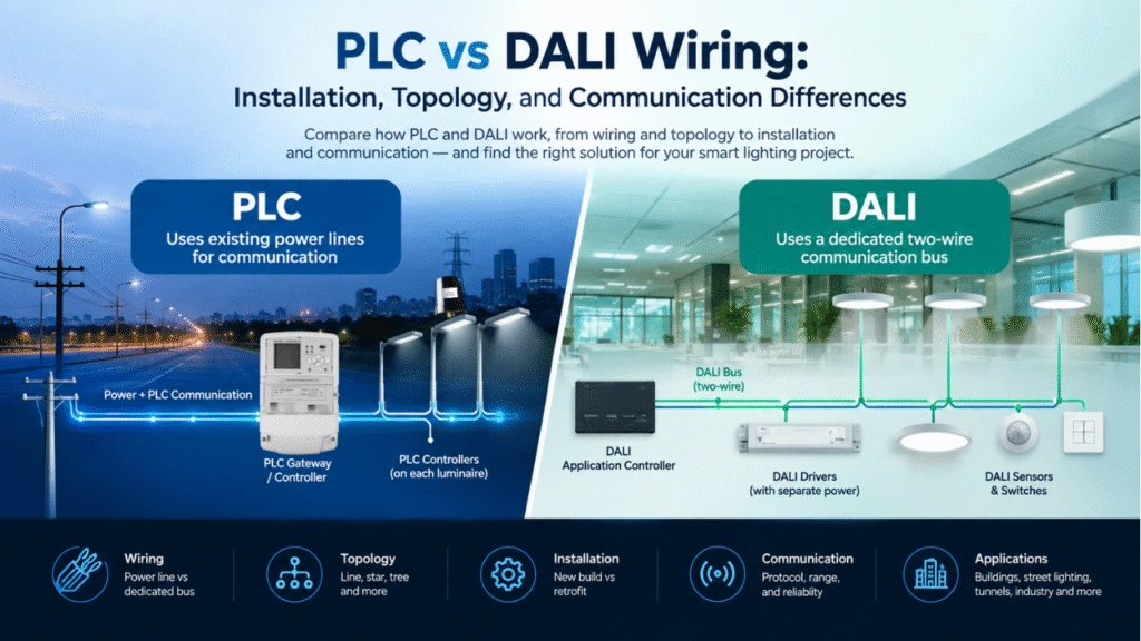
Each device communicates over existing power cables, eliminating the need for additional communication wiring.
Why Network Capacity Matters
An oversized network can lead to:
- Increased communication latency
- Lower polling frequency
- Packet retransmission
- Reduced real-time performance
- Higher maintenance costs
A properly sized network provides:
- Stable communication
- Fast response time
- Reliable dimming commands
- Accurate fault detection
- Easier future expansion
Key Factors Affecting PLC Network Capacity
1. Number of Devices
Every controller occupies communication bandwidth.
Example devices include:
- Street light controllers
- LED drivers
- Loop controllers
- AI cameras
- Smart sensors
- Metering devices
The total number of nodes directly affects polling time.
2. Communication Interval
Ask yourself:
How often should every light report data?
Typical settings:
| Reporting Interval | Typical Application |
|---|---|
| Every 5 seconds | Real-time monitoring |
| Every 30 seconds | Smart city |
| Every minute | Municipal lighting |
| Every 5 minutes | Energy monitoring |
Longer intervals allow significantly larger networks.
3. Data Packet Size
Different devices transmit different amounts of information.
Example:
Basic controller
- ON/OFF status
- Brightness
- Voltage
- Current
- Power
≈ 40–80 bytes
AI Vision Sensor
- Detection results
- Occupancy
- Events
- Alarm data
Much larger packets.
4. Communication Speed
Modern PLC modules using OFDM modulation provide much higher throughput than traditional narrowband PLC systems.
Effective throughput depends on:
- Line quality
- Electrical noise
- Distance
- Number of repeaters
- Network loading
Actual engineering performance is more important than theoretical maximum speed.
5. Electrical Topology
Capacity also depends on network structure.
Common topologies include:
- Linear street lighting
- Branch distribution
- Ring distribution
- Industrial distribution panels
Complex branching usually increases communication overhead.
Basic PLC Network Capacity Formula
A simplified estimation formula is:
Maximum Nodes ≈

Available Communication Time

÷

Average Communication Time per Node
Where
Communication Time per Node includes:
- Command transmission
- Response
- Error checking
- Retransmission margin
This provides a practical engineering estimate during system planning.
Example Capacity Calculation
Imagine a municipal street lighting project.
Project specifications:
- 600 street lights
- One PLC controller per light
- Status upload every 60 seconds
- Remote dimming
- Fault reporting
Estimated communication:
Each controller:
- 60 bytes upload
- 40 bytes command
Total traffic:
600 × 100 bytes
= 60,000 bytes
Distributed over one minute:
≈ 1 KB per second
This traffic level is well within the capability of a modern PLC lighting system when the electrical environment is properly designed.
Example PLC Network Segmentation Strategy
Although the theoretical capacity may be much higher, engineering practice recommends dividing large projects into manageable sections. These values are planning examples rather than universal PLC limits. Actual network size should be validated according to PLC module performance, electrical topology, communication interval, interference level, and project requirements.
Example:
| Project Size | Recommended Design |
|---|---|
| 100 lights | Single gateway with cloud management |
| 300 lights | Single PLC network with cloud management |
| 500 lights | Double gateways with cloud management |
| 1000+ lights | Multiple gateways with cloud management |
| 5000+ lights | Multiple gateways with cloud management |
Segmenting networks simplifies maintenance and improves reliability.
Capacity Planning for Future Expansion
Always reserve network capacity.
Recommended spare capacity:
20%–30%
Example:
Current installation:
400 lights
Design capacity:
500–550 lights
This avoids replacing gateways during future expansion.
Communication Load Considerations
Not every device communicates equally.
Typical priorities:
High Priority
- Alarm messages
- Fault detection
- Emergency commands
Medium Priority
- Switching
- Dimming
- Scheduling
Low Priority
- Energy reports
- Historical statistics
- Maintenance logs
Modern PLC systems prioritize critical messages to maintain system responsiveness.
Best Practices for Large PLC Lighting Projects
For projects involving thousands of lighting points:
- Divide networks by electrical distribution area.
- Install PLC gateways close to load centers.
- Avoid excessively long feeder circuits.
- Use signal couplers where necessary.
- Minimize electrical interference.
- Reserve bandwidth for future devices.
- Regularly monitor communication quality through the cloud platform.
These practices help ensure reliable operation and simplify long-term maintenance. If you are new user, can see our PLC Smart Lighting System Architecture Guide.
Typical PLC Capacity by Application
| Application | Recommended Nodes per Network |
|---|---|
| Residential Community | 100–300 |
| Street Lighting | 300–500 |
| Industrial Park | 200–400 |
| Tunnel Lighting | 100–300 |
| Warehouse | 150–400 |
| Campus | 200–500 |
| Port Lighting | 200–400 |
| Airport Lighting | Project dependent |
Actual capacity varies depending on communication frequency, electrical environment, and network architecture.
Why MicroNature PLC Solutions Support Large-Scale Networks
MicroNature’s PLC smart lighting solutions are designed for demanding municipal and industrial environments.
Key advantages include:
- Utilizes existing power lines without additional communication cables
- Fast PLC mesh networking
- Remote monitoring through a cloud SaaS platform
- Real-time dimming and scheduling
- Open API for integration with third-party systems
- Supports AI vision sensors and environmental sensors
- Reliable communication in electrically noisy environments
- Scalable architecture suitable for smart city deployments
These capabilities enable engineers to build flexible networks that can grow with future project requirements.