Designing a reliable Power Line Communication (PLC) network requires more than knowing the cable length. Communication distance depends on cable quality, electrical noise, network topology, transformers, branching, and connected devices.
This guide introduces a practical PLC Communication Distance Calculator that helps engineers estimate achievable communication range before deployment. While every installation requires field verification, this calculator provides an excellent starting point for planning smart lighting, industrial automation, EV charging, and smart city PLC projects.
Why PLC Communication Distance Cannot Be Measured by Cable Length Alone
Unlike Ethernet, PLC signals travel over electrical wiring that was never designed for data transmission.
Several factors reduce signal quality as distance increases:
- Cable resistance
- Signal attenuation
- Branching circuits
- Electrical interference
- Transformers
- Switching power supplies
- LED drivers
- Motors
- Variable frequency drives (VFDs)
- Harmonic distortion
For this reason, a 1 km cable in one installation may communicate perfectly, while another 300 m installation may experience unstable communication.
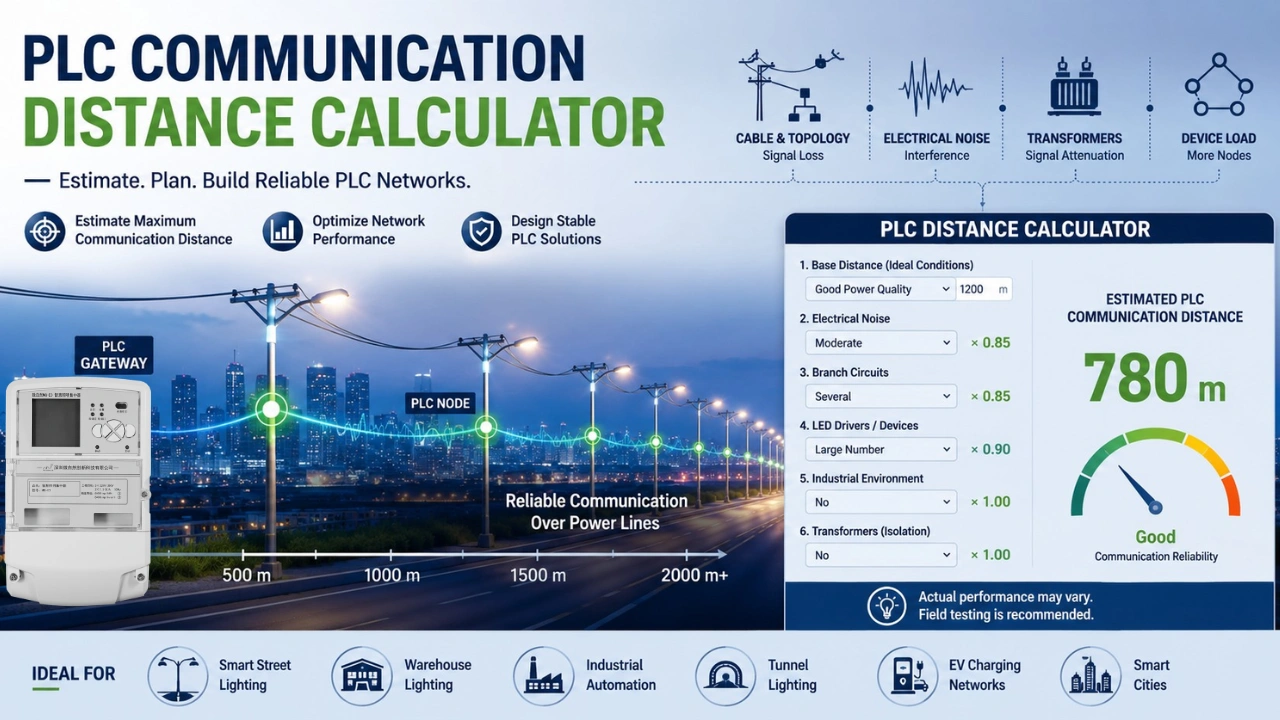
PLC Communication Distance Calculator
Use the following engineering formula as a planning tool.
Step 1: Base Distance
Choose a theoretical maximum distance under ideal conditions.
| Network Condition | Base Distance |
|---|---|
| Excellent power quality | 1500 m |
| Good power quality | 1200 m |
| Normal commercial building | 800 m |
| Industrial environment | 500 m |
Step 2: Apply Reduction Factors
Multiply the base distance by each applicable factor.
| Factor | Multiplier |
|---|---|
| Clean power line | ×1.00 |
| Moderate electrical noise | ×0.85 |
| Heavy electrical noise | ×0.60 |
| Multiple branch circuits | ×0.85 |
| Large number of LED drivers | ×0.90 |
| Industrial motors nearby | ×0.75 |
| Passing through transformer | ×0.00 (unless bridge equipment is installed) |
Example Calculation
Assume:
- Base distance = 1200 m
- Moderate electrical noise
- Several branch circuits
- Large LED lighting network
Estimated distance:
1200 × 0.85 × 0.85 × 0.90
≈ 780 meters
This suggests the PLC network should communicate reliably over approximately 780 meters under these conditions.
PLC Distance Estimation Table
| Environment | Estimated Stable Distance |
|---|---|
| Residential | 800–1500 m |
| Commercial Building | 500–1000 m |
| Office Building | 500–900 m |
| Street Lighting | 800–2000 m |
| Industrial Factory | 300–800 m |
| Warehouse | 500–1200 m |
| Tunnel Lighting | 500–1500 m |
These values are engineering estimates and should be validated with on-site testing.
Factors Affecting PLC Communication Distance
1. Cable Quality
New copper cables generally provide lower attenuation than aging or corroded conductors.
Better cable quality results in:
- Lower signal loss
- Higher SNR
- Better communication stability
2. Cable Cross-Section
Larger conductors typically exhibit lower resistance and can improve communication performance over long distances.
3. Electrical Noise
Noise sources include:
- LED drivers
- Motor drives
- Inverters
- Elevators
- Welding equipment
- Air conditioners
The more electrical noise, the shorter the communication distance.
4. Network Topology
A straight cable performs better than one with many branches. If you are a new user, please check our article PLC Smart Lighting System Architecture Guide.
Poor topology causes:
- Signal reflection
- Signal splitting
- Additional attenuation
5. Number of Connected Devices
Each PLC node adds a small electrical load to the communication network.
Large deployments with hundreds of devices may require repeaters or optimized network segmentation.
6. Transformer Isolation
Standard power transformers typically block high-frequency PLC signals.
For networks spanning multiple transformers, engineers commonly deploy gateways, repeaters, or bridge devices to maintain communication.
Typical PLC Communication Distances
Smart Street Lighting
Typical range:
800–2000 meters
Depending on:
- Pole spacing
- Distribution cabinet design
- Electrical noise
Warehouse Lighting
Typical range:
500–1200 meters
Usually benefits from long cable runs and fewer branches.
Tunnel Lighting
Typical range:
500–1500 meters
Distance depends on:
- Driver quality
- Cable routing
- Tunnel electrical equipment
Industrial Plants
Typical range:
300–800 meters
High electrical noise often limits transmission distance.
Improving PLC Communication Distance
Engineers can significantly increase communication reliability by following these best practices:
Reduce Electrical Noise
- Use high-quality LED drivers
- Install EMI filters where appropriate
- Separate noisy equipment from communication circuits
Optimize Cable Layout
Avoid unnecessary branches.
Whenever possible:
- Use radial topology
- Minimize cable discontinuities
Divide Large Networks
Instead of one extremely large PLC network:
- Create multiple PLC segments
- Connect them using gateways
This improves both communication quality and maintenance efficiency.
Select Industrial PLC Modules
Professional PLC communication modules generally provide:
- Better receiver sensitivity
- Improved OFDM performance
- Enhanced error correction
- Adaptive networking
- Greater resistance to electrical interference
To select a right PLC module, you can check our article PLC Module vs PLC Chipset: Key Differences Explained.