PLC and DALI are two different technologies that can complement each other in a smart lighting system.
Power Line Communication (PLC) uses existing electrical power lines to transmit data, making it useful for connecting distributed lighting controllers without installing a separate communication cable.
DALI (Digital Addressable Lighting Interface) is a digital lighting-control technology designed for communication with lighting control gear and other devices. DALI-2 extends the standardized ecosystem to include control devices, application controllers, input devices, and other components based on the IEC 62386 standard family.
Instead of choosing between PLC and DALI, system designers can combine them:
PLC provides the network communication layer, while DALI provides local luminaire-level lighting control.
A typical hybrid architecture can be:
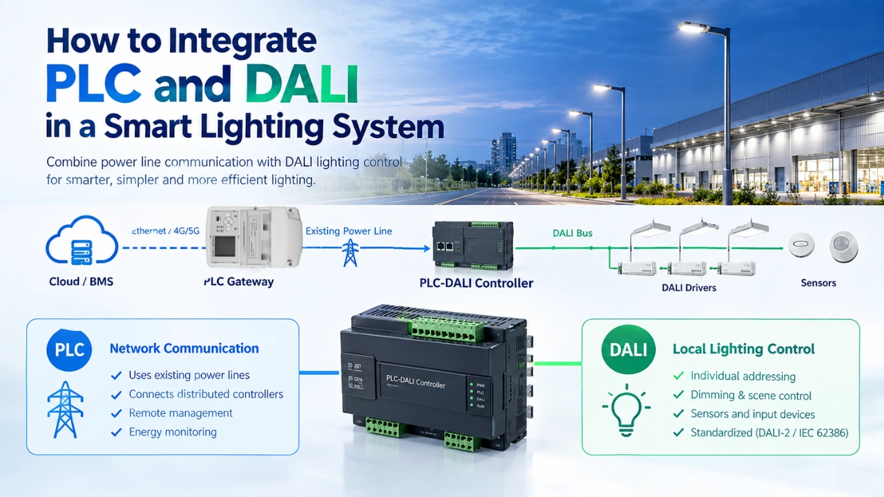
Cloud Platform → PLC Gateway → Power Line → PLC-DALI Controller → DALI Bus → DALI Drivers / Sensors
This architecture can be useful when a project needs centralized remote management over existing electrical infrastructure while maintaining DALI-based control at the luminaire or room level.
Quick Answer: Can PLC and DALI Work Together?
Yes. PLC and DALI can be integrated into the same smart lighting system.
They normally perform different functions:
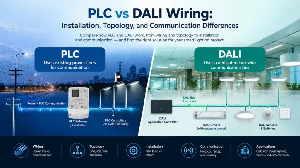
| Function | PLC | DALI |
|---|---|---|
| Main communication medium | Existing power lines | Dedicated DALI bus |
| Typical role | Network-level communication | Local lighting control |
| Remote communication | Yes, through PLC gateway/network | Usually requires another network interface |
| Luminaire control | Through a PLC lighting controller | Directly controls compatible DALI gear |
| Additional communication cable | Often not required for the PLC network | DALI bus wiring is required locally |
| Individual lighting control | Depends on controller/driver architecture | Supported |
| Group control | Supported | Supported |
| Local sensors | Through compatible PLC controller | DALI input devices can be integrated |
| Cloud connection | Through gateway | Requires an upper-level gateway/controller |
| Typical application | Street, tunnel, industrial, outdoor networks | Buildings, rooms, luminaires, local lighting zones |
| Hybrid application | Network/backhaul | Local lighting-control layer |
The important point is that PLC and DALI are not necessarily direct alternatives. PLC describes a communication technology using power lines, while DALI is a standardized digital lighting-control system.
1. What Is PLC in a Smart Lighting System?
Power Line Communication allows digital data to travel through electrical power wiring.
A simplified PLC lighting architecture is:
Cloud Platform
↓
PLC Gateway / Concentrator
↓
Existing Power Line
↓
PLC Lighting Controller
↓
LED Driver / Luminaire
The same electrical infrastructure provides both power and communication.
A PLC smart lighting system can therefore support functions such as:
- Remote ON/OFF control
- Dimming
- Scheduling
- Energy monitoring
- Fault detection
- Device status monitoring
- Group control
- Remote configuration
- Sensor integration
For large outdoor or industrial lighting networks, this architecture can reduce the need for separate communication cabling.
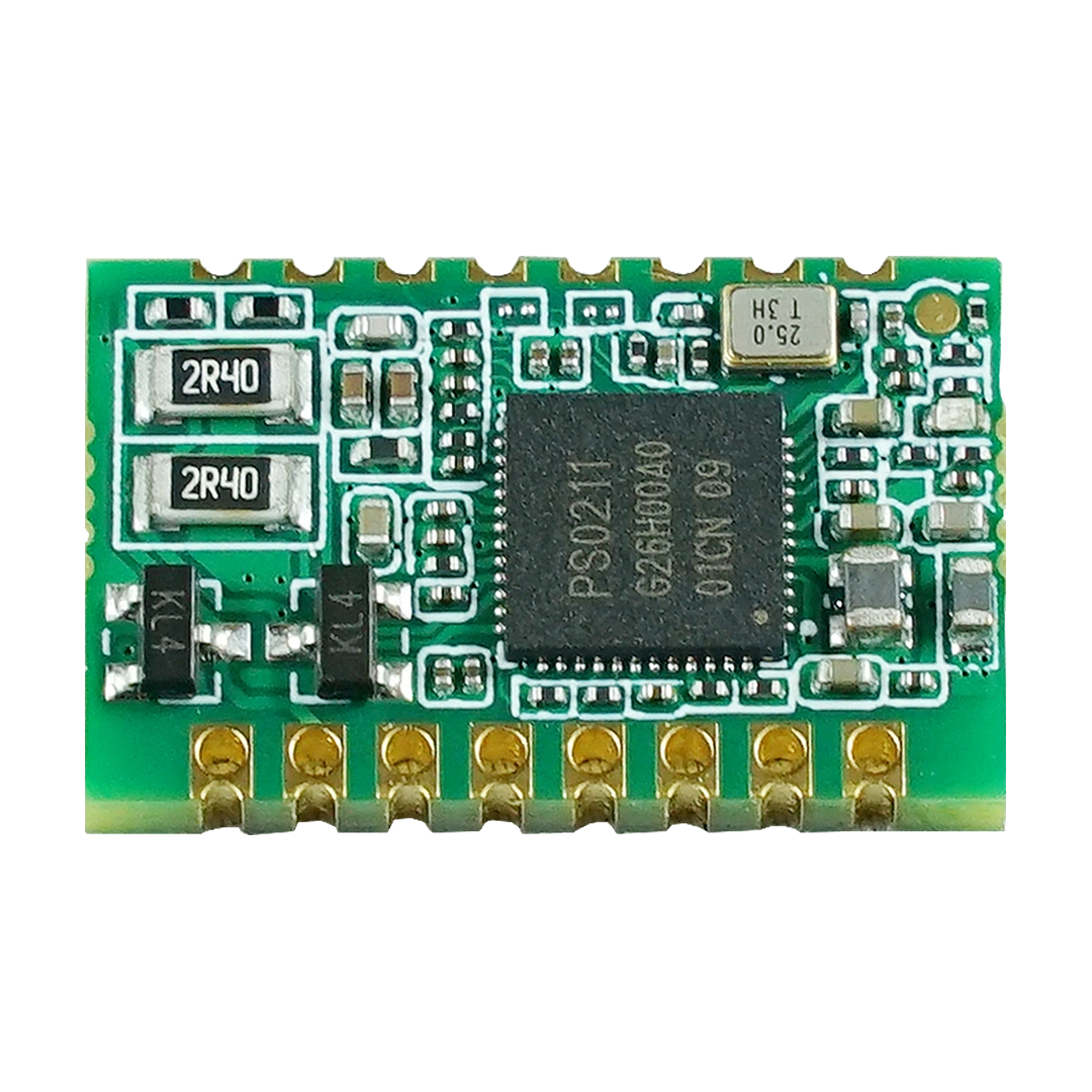
Embedded PLC modules can also be integrated directly into lighting controllers and electrical products. For example, MicroNature’s PLC modules provide interfaces such as UART, PWM and GPIO for OEM controller designs.
2. What Is DALI in a Smart Lighting System?
DALI is a digital lighting-control system designed specifically for lighting applications.
A DALI system can connect lighting control gear such as LED drivers with control devices and application controllers.
DALI-2 also supports standardized input devices, including occupancy and light sensors, as well as other control components.
A simplified DALI system looks like:
DALI Controller
↓
DALI Bus
↓
DALI LED Drivers
Sensors and other input devices can also participate in the DALI control architecture.
DALI is particularly useful when a lighting system requires functions such as:
- Individual luminaire addressing
- Group control
- Dimming
- Scene control
- Lighting status information
- Local sensors
- Standardized lighting-device communication
PLC vs DALI for Street Lighting: Which Is Better? This article may help you know more about the difference between PLC and DALI.
3. Why Integrate PLC and DALI?
The main reason to integrate PLC and DALI is to combine longer-range network communication with local standardized lighting control.
Consider a large industrial facility.
Hundreds of luminaires may be distributed across different areas. Installing a dedicated communication network throughout the entire facility may increase installation complexity.
A hybrid system can instead use:
PLC for communication between distributed lighting zones
and:
DALI for communication between the local controller and DALI lighting devices.
The architecture can look like this:
                 Cloud / CMS
                      │
                      │ Ethernet / 4G / 5G
                      ▼
                PLC Gateway
                      │
                      │
              Existing Power Line
        ┌─────────────┼─────────────┐
        │             │             │
        ▼             ▼             ▼
   PLC Controller PLC Controller PLC Controller
        │             │             │
      DALI          DALI          DALI
        │             │             │
   ┌────┴────┐   ┌────┴────┐   ┌────┴────┐
   ▼    ▼    ▼   ▼    ▼    ▼   ▼    ▼    ▼
 Driver Driver Driver Driver Driver Driver
In this architecture:
- Cloud/CMS manages the complete lighting network.
- PLC Gateway connects the management platform to the electrical network.
- PLC transports communication through the power infrastructure.
- PLC-DALI Controller converts network commands into DALI commands.
- DALI controls local drivers and compatible lighting devices.
This creates a layered smart lighting architecture instead of forcing one communication technology to perform every function.
4. Basic PLC-DALI Integration Architecture
There are several ways to implement PLC and DALI integration. PLC Smart Lighting Topology Explained: Full System Architecture Guide this article will show you how PLC work in smart lighting application.
The most common architecture for a distributed smart lighting system is a PLC-to-DALI gateway or controller.
Architecture
Cloud Platform
      │
      ▼
PLC Gateway
      │
      ▼
Power Line Communication
      │
      ▼
PLC-DALI Controller
      │
      ▼
DALI Bus
   ┌──┼──┐
   ▼  ▼  ▼
DALI DALI DALI
Driver Driver Driver
   │  │  │
   ▼  ▼  ▼
 LED LED LED
The PLC-DALI controller performs protocol conversion.
For example:
Cloud command:
Set Light 25 to 40% brightness.
The command travels through the PLC network to the local controller.
The controller then translates the command into an appropriate DALI command for the target lighting device.
The response or status information can travel in the opposite direction:
DALI Driver → PLC-DALI Controller → PLC Network → Gateway → Cloud
This enables centralized monitoring while retaining local DALI control.
5. How Does a PLC-DALI Gateway Work?
A PLC-DALI gateway generally contains four functional sections:
1. PLC Communication Interface
The PLC interface communicates with the upstream PLC network.
It may use an embedded PLC module connected to the controller’s MCU.
A simplified hardware structure is:
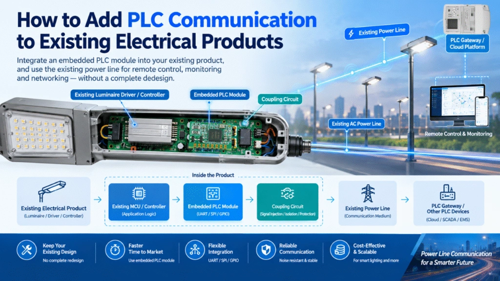
MCU ↔ PLC Module ↔ PLC Coupling Circuit ↔ AC Power Line
An embedded PLC module can provide the communication interface while the host MCU handles application-specific lighting logic.
2. DALI Interface
The controller also contains a DALI interface connected to the local DALI bus.
The DALI interface communicates with:
- DALI LED drivers
- DALI control gear
- DALI sensors
- Other compatible DALI devices
3. Application Processor
The MCU or processor manages the relationship between the PLC and DALI layers.
It can:
- Receive PLC commands
- Parse lighting instructions
- Generate DALI commands
- Read DALI status
- Process sensor information
- Manage local schedules
- Report device status
- Handle communication errors
4. Power and Protection
The controller also needs appropriate:
- AC/DC power supply
- Surge protection
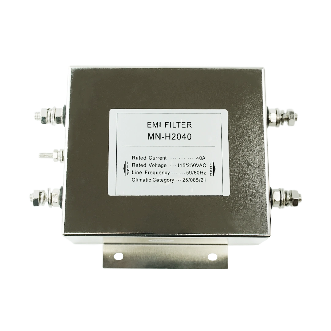
- EMI filtering
- Electrical isolation where required
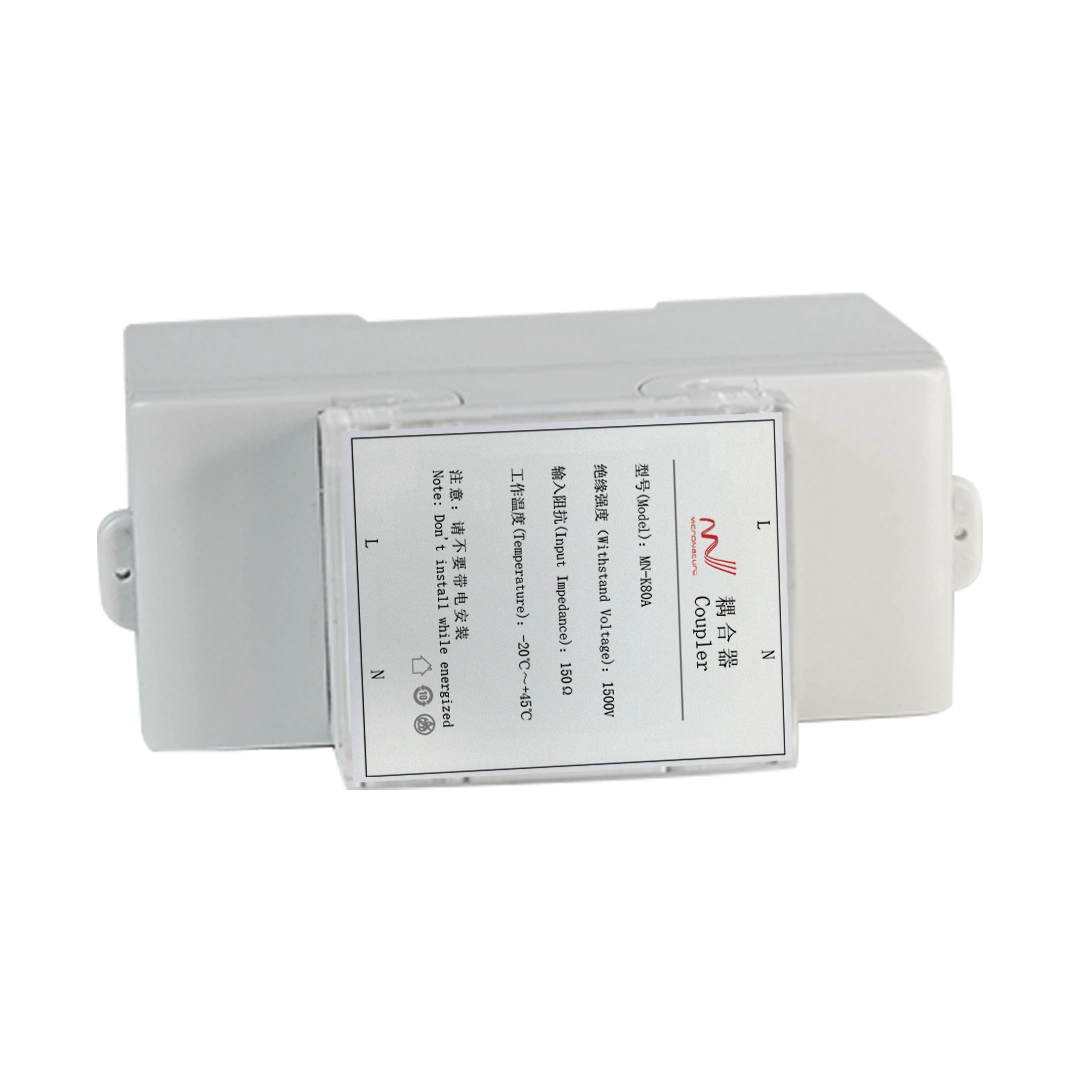
- PLC coupling circuitry
- DALI bus power/interface circuitry
The exact design depends on the electrical environment and applicable safety requirements.
6. PLC and DALI Communication Workflow
A hybrid system can process a lighting command in several stages.
Step 1: User Sends a Command
An operator changes a lighting level through a cloud platform or mobile application.
For example:
Warehouse Zone A → Brightness = 30%
Step 2: Cloud Sends the Command to the Gateway
The cloud platform sends the command to the PLC gateway through Ethernet, cellular communication, or another suitable network connection.
Step 3: PLC Transmits the Command
The gateway sends the command through the PLC network.
The data travels over the existing electrical infrastructure.
Step 4: Local PLC Controller Receives the Command
The PLC-DALI controller receives the message.
The controller identifies:
- Target lighting zone
- Target device
- Required brightness
- Command type
Step 5: Controller Converts the Command to DALI
The controller translates the application command into the required DALI operation.
For example:
PLC command → DALI dimming command
Step 6: DALI Driver Adjusts the Light
The DALI driver receives the command and changes the LED output.
Step 7: Status Returns to the Cloud
If the system supports feedback, the local controller can collect device status and transmit it back through PLC.
The overall process becomes:
Cloud → PLC Gateway → PLC → PLC-DALI Controller → DALI Driver
and:
DALI Driver → PLC-DALI Controller → PLC → Gateway → Cloud
7. Where Should the PLC-DALI Gateway Be Installed?
The gateway/controller location depends on the lighting architecture.
Option 1: Inside the Luminaire
The PLC-DALI electronics can be integrated into or near the luminaire.
This approach can provide:
- Compact installation
- Local DALI driver control
- Individual luminaire communication
- Reduced external control hardware
For OEM lighting manufacturers, an embedded PLC module can be integrated into the lighting controller or driver architecture.
Option 2: Inside a Lighting Control Cabinet
For industrial, warehouse, tunnel, or infrastructure projects, the PLC-DALI controller can be installed inside a local electrical cabinet.
The architecture can be:
Power Cabinet → PLC → Local PLC-DALI Controller → DALI Bus → Multiple Drivers
This can be useful when several DALI luminaires belong to one local control zone.
Option 3: Distributed Controllers
A large facility can use multiple PLC-DALI controllers.
For example:
                Cloud
                  │
             PLC Gateway
                  │
        ───────── Power Line ─────────
          │             │             │
          ▼             ▼             ▼
      Zone A         Zone B         Zone C
      PLC-DALI       PLC-DALI       PLC-DALI
          │             │             │
       DALI Bus      DALI Bus      DALI Bus
          │             │             │
      20 Lamps       30 Lamps       15 Lamps
This architecture allows the network to be divided into manageable local lighting zones.
8. PLC + DALI for Retrofit Smart Lighting
One of the most interesting applications is upgrading existing lighting infrastructure.
A traditional system may have:
AC Power → LED Driver → Luminaire
A smart retrofit architecture can become:
AC Power + PLC Communication → PLC Controller → DALI Driver
The PLC network can use the existing electrical infrastructure for communication, while DALI can provide local digital control where DALI-compatible drivers are installed.
This can be particularly useful when a project needs centralized management but does not want to install a new communication network throughout the entire facility.
However, the existing electrical topology must be evaluated before deployment. PLC communication performance depends on the characteristics of the power network, electrical loads, noise environment, coupling design, and network topology.
9. PLC-DALI Integration for Street Lighting
A hybrid PLC-DALI architecture can also be considered for outdoor lighting.
For example:
Smart Lighting Cloud
        │
        ▼
   PLC Gateway
        │
        ▼
Street Lighting Power Line
        │
 ┌──────┼──────┐
 ▼      ▼      ▼
PLC    PLC    PLC
Node   Node   Node
 │      │      │
DALI   DALI   DALI
 │      │      │
LED    LED    LED
Driver Driver Driver
In this model, PLC can provide communication between the central gateway and distributed lighting nodes, while DALI provides local driver-level control.
Potential functions include:
- Remote dimming
- Scheduling
- Group control
- Energy monitoring
- Fault reporting
- Local driver control
- Sensor integration
For street-lighting projects, however, system designers should evaluate whether DALI is needed at every luminaire. In some outdoor systems, a PLC lighting controller can communicate directly with a dimmable LED driver, making a separate DALI layer unnecessary.
The appropriate architecture depends on the selected driver, controller, network topology, and project requirements.
10. PLC-DALI Integration for Industrial and Warehouse Lighting
Industrial facilities are another potential application.
A warehouse may contain:
- Hundreds of LED fixtures
- High ceilings
- Long cable runs
- Multiple electrical distribution zones
- Occupancy sensors
- Daylight sensors
- Emergency lighting
- Centralized energy management
A hybrid system could use PLC as the facility-wide communication layer and DALI as the local lighting-control interface.
For example:
PLC network: connects lighting zones
DALI network: manages local drivers
Sensors: provide occupancy or light-level information
Cloud/BMS: provides centralized monitoring and management
This creates a layered architecture:
           Cloud / BMS
                │
         PLC Communication
                │
        ┌───────┼───────┐
        ▼       ▼       ▼
      Zone A  Zone B  Zone C
        │       │       │
      DALI    DALI    DALI
        │       │       │
     Drivers Drivers Drivers
        │       │       │
      LEDs    LEDs    LEDs
11. What Hardware Is Needed?
A typical PLC-DALI smart lighting system may include the following components.
Central System
- Cloud platform or CMS
- PLC gateway/concentrator
- Ethernet or cellular backhaul
PLC Layer
- PLC communication module
- PLC lighting controller
- PLC coupling circuit
- EMI/filtering and protection components
DALI Layer
- DALI controller/interface
- DALI bus power supply where required by the system architecture
- DALI LED drivers
- DALI sensors or input devices where applicable
Lighting Layer
- LED luminaires
- LED drivers
- Sensors
- Emergency lighting or other specialized equipment
The exact component list depends on whether the system uses DALI, DALI-2, or another compatible lighting-control architecture.
12. How to Design a PLC-DALI Controller
For OEM manufacturers developing their own PLC-DALI product, the controller can be divided into several functional blocks.
                AC Input
                   │
        ┌──────────┴──────────┐
        │                     │
   Power Supply        PLC Coupling
        │                     │
        ▼                     ▼
      Host MCU ◄────────► PLC Module
        │
        │
        ▼
    DALI Interface
        │
        ▼
     DALI Bus
        │
   ┌────┼────┐
   ▼    ▼    ▼
 Driver Driver Sensor
The host MCU acts as the application processor.
The PLC module handles power-line communication.
The DALI interface handles local lighting communication.
This modular architecture can simplify OEM development because the PLC communication function and lighting application function can be separated.
For example, MicroNature’s embedded PLC modules are designed for integration into smart lighting controllers and other electrical products, with interfaces such as UART, PWM and GPIO depending on the module.
13. Important Hardware Design Considerations
Integrating PLC and DALI is not simply a matter of connecting two communication interfaces.
Several hardware issues should be evaluated.
PLC Coupling
The PLC signal must be coupled to the power line correctly. If you are a new user, please first check this article PLC Coupling Circuit Design Guide for Embedded PLC Devices.
The coupling circuit should be designed according to:
- Operating voltage
- PLC frequency band
- Required signal level
- Isolation requirements
- Surge environment
- EMI requirements
- Power-line impedance
The coupling network is particularly important because the power line simultaneously carries high-voltage electrical power and PLC communication signals.
DALI Interface
The DALI interface should be designed according to the applicable DALI system requirements and the selected devices.
Consider:
- Bus power
- Bus voltage
- Wiring
- Device loading
- Polarity requirements of the implementation
- Protection
- Isolation
- Communication timing
EMI and Surge Protection
Smart lighting equipment can be exposed to:
- Switching power supplies
- LED drivers
- Motors
- Relays
- Long cable runs
- Lightning-induced surges
- Industrial electrical noise
Therefore, both the PLC and DALI sections need appropriate protection and EMC design.
14. Firmware and Software Architecture
A PLC-DALI controller also needs a software architecture that separates communication from application logic.
A practical structure is:
Application Layer
│
├── Lighting Control
├── Scheduling
├── Sensor Logic
├── Group Management
└── Fault Management
        │
        ▼
Protocol Management
│
├── PLC Protocol
└── DALI Protocol
        │
        ▼
Hardware Abstraction Layer
│
├── PLC Module
├── DALI Interface
├── GPIO
└── UART / Other Interfaces
This architecture makes it easier to modify the lighting application without redesigning the complete communication system.
For example, the same PLC hardware platform could potentially be used with different local lighting interfaces depending on the target product.
15. Common PLC-DALI Integration Challenges
Challenge 1: Treating PLC and DALI as Direct Competitors
PLC and DALI have different roles.
A better approach is to define the architecture first:
What needs to communicate over the entire facility?
What needs to communicate locally with the luminaire?
If PLC is suitable for the network layer and DALI is required at the luminaire layer, a hybrid architecture may make sense.
Challenge 2: Adding DALI When It Is Not Necessary
Not every PLC lighting system needs DALI.
If a PLC controller can directly control the selected LED driver using another supported interface, adding DALI may increase hardware and software complexity without providing a corresponding benefit.
Therefore, DALI should be included when its features or device ecosystem are actually required.
Challenge 3: Ignoring the Electrical Network
PLC communication performance is strongly related to the actual power network.
Engineers should evaluate:
- Cable length
- Electrical topology
- Phase configuration
- Noise sources
- Switching loads
- Filters
- Transformers
- Circuit breakers
- Surge protection
- Coupling paths
A PLC system should be tested under realistic electrical operating conditions rather than only on a laboratory bench.
Challenge 4: Assuming All DALI Devices Behave Identically
A hybrid controller should be tested with the actual DALI drivers and devices selected for the project.
Compatibility testing should include:
- Dimming
- ON/OFF
- Device addressing
- Group control
- Scenes
- Status feedback
- Fault conditions
- Power cycling
- Communication recovery
- 16. PLC vs DALI vs PLC + DALI
The three architectures can be understood as follows:
| Architecture | Communication Structure | Typical Strength |
|---|---|---|
| PLC only | PLC network → lighting controller | Distributed network communication over existing power lines |
| DALI only | DALI controller → DALI bus → drivers | Local digital lighting control |
| PLC + DALI | PLC network → PLC-DALI controller → DALI bus | Centralized network + local DALI control |
The hybrid approach is therefore not automatically better. It is useful when the project benefits from the combination of both layers.
17. When Should You Use a PLC-DALI Architecture?
A PLC-DALI architecture may be worth considering when a project has several of the following requirements:
- Large distributed lighting network
- Existing electrical wiring
- Need for centralized management
- DALI-compatible LED drivers
- Local luminaire-level control
- Multiple lighting zones
- Remote monitoring
- Energy management
- Sensor integration
- Retrofit requirements
- Limited feasibility for additional communication cabling
For a small room with several DALI luminaires, a conventional DALI architecture may be sufficient.
For a large outdoor network where the lighting controller already communicates directly with the driver, adding DALI may also be unnecessary.
The right choice should be based on the required architecture rather than simply combining technologies.
18. Example: PLC-DALI Smart Lighting System
Consider a warehouse with 300 LED luminaires.
The project requires:
- Centralized control
- Individual or group dimming
- Occupancy-based lighting
- Energy monitoring
- Remote fault detection
- No new communication cable throughout the warehouse
A possible architecture is:
                  Cloud Platform
                       │
                 Ethernet / 4G
                       │
                       ▼
                  PLC Gateway
                       │
             Existing Power Network
                       │
       ┌───────────────┼───────────────┐
       ▼               ▼               ▼
   PLC-DALI A      PLC-DALI B      PLC-DALI C
       │               │               │
    DALI Bus        DALI Bus        DALI Bus
       │               │               │
   100 Lamps       100 Lamps       100 Lamps
       │               │               │
   Sensors          Sensors          Sensors
The PLC network provides the distributed communication infrastructure.
Each local PLC-DALI controller manages its own DALI lighting zone.
The cloud platform can then manage the entire warehouse as one system.
19. PLC-DALI Integration for OEM Lighting Products
Lighting manufacturers can also integrate PLC and DALI directly into their products.
A smart lighting controller could contain:
MCU + PLC Module + DALI Interface + LED Driver Interface
The PLC module provides communication through the power line.
The MCU manages application logic.
The DALI interface communicates with DALI devices.
This approach can allow manufacturers to develop a customized smart lighting product without designing the PLC communication chipset and RF/wired communication architecture from the beginning.
For example, an embedded PLC module such as the MN-L80C can be used as the PLC communication component of a customized controller architecture. The module supports interfaces including UART, PWM and GPIO and is designed for embedded smart-lighting and industrial applications.
20. Recommended Development Process
For an OEM developing a PLC-DALI product, the development process can be divided into seven stages.
Stage 1: Define the System Architecture
Determine:
- PLC network topology
- DALI topology
- Number of lighting nodes
- Number of DALI devices
- Gateway requirements
- Cloud/BMS interface
Stage 2: Select the PLC Module
Evaluate:
- Communication performance
- Interface requirements
- Operating environment
- PCB size
- Firmware support
- Coupling architecture
Stage 3: Select DALI Hardware
Select compatible:
- DALI drivers
- DALI interfaces
- Sensors
- Controllers
- Bus power components
Stage 4: Design the Hardware
Integrate:
- Power supply
- PLC module
- PLC coupling circuit
- MCU
- DALI interface
- Protection circuits
Stage 5: Develop Firmware
Implement:
- PLC communication
- DALI communication
- Device addressing
- Lighting commands
- Sensor processing
- Fault handling
- Communication recovery
Stage 6: Test the System
Test under:
- Different cable lengths
- Different electrical loads
- Different lighting drivers
- Different DALI devices
- High-noise conditions
- Power cycling
- Surge/EMI conditions
- Maximum network size
Stage 7: Pilot Deployment
Deploy a small number of nodes before mass production.
Measure:
- Communication stability
- Response time
- Dimming performance
- Device compatibility
- Energy data accuracy
- Fault reporting
- Long-term reliability