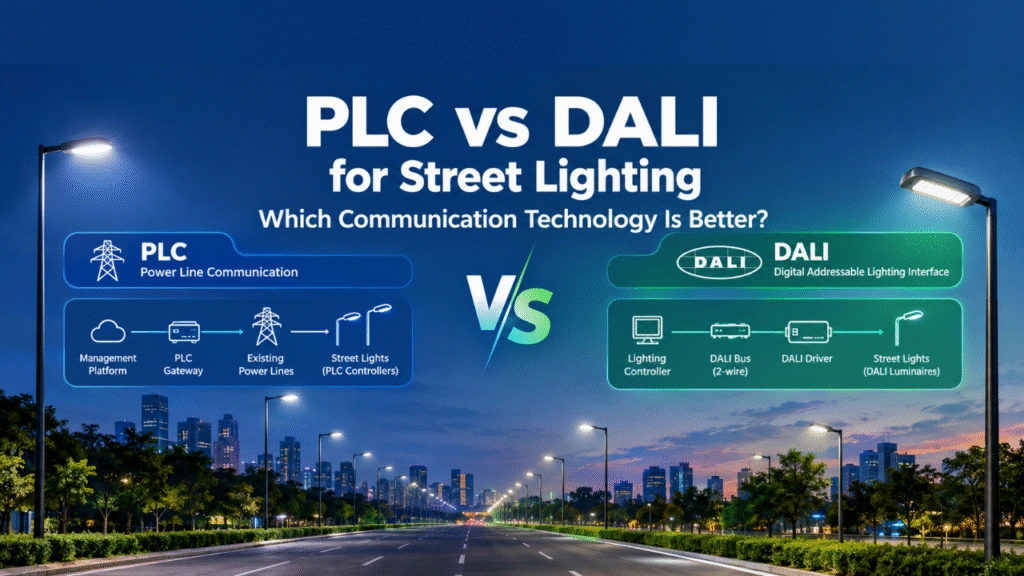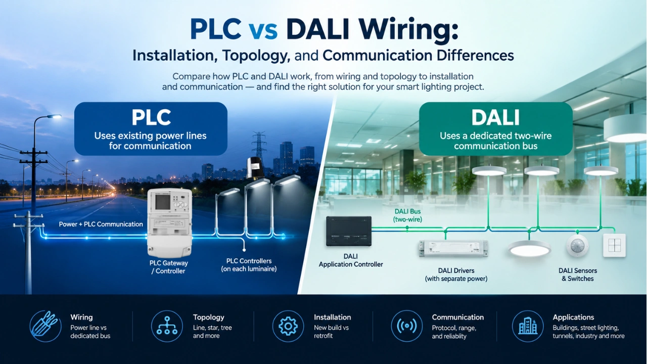
At a Glance: PLC uses existing power wiring for communication, making it attractive for lighting retrofits and large infrastructure networks. DALI uses a dedicated two-wire bus and is well suited to structured lighting-control systems, especially in buildings. PLC vs DALI for Street Lighting: Which Is Better? This article explain more details.
When designing a smart lighting system, choosing the communication technology can significantly affect wiring, installation time, scalability, and long-term maintenance.
PLC (Power Line Communication) and DALI (Digital Addressable Lighting Interface) take fundamentally different approaches to lighting communication.
DALI uses a dedicated two-wire communication bus that carries both communication data and bus power. PLC, by contrast, transmits communication signals over the existing electrical power conductors, allowing the same power wiring to serve as the communication medium.
The main wiring difference between PLC and DALI is that PLC transmits communication over existing electrical power lines, while DALI uses a dedicated two-wire communication bus.
This difference becomes especially important in street lighting, tunnels, industrial facilities, warehouses, parking areas, power plants, and other large infrastructure projects.
PLC vs DALI Wiring: Quick Comparison
The fundamental difference is simple:
DALI requires a dedicated communication bus, while PLC uses the existing power line as the communication path.
| Feature | PLC Lighting | DALI / DALI-2 |
|---|---|---|
| Communication medium | Existing power line | Dedicated two-wire DALI bus |
| Separate communication wiring | Usually not required | Required |
| Power and communication | Same power conductors | DALI bus carries communication and bus power; luminaire power remains separate |
| Typical topology | Based on electrical power network | Line, star, tree, or combinations |
| Maximum DALI bus distance | — | Typically 300 m between furthest devices under specified conditions |
| DALI device capacity | — | Up to 64 control gear + 64 control devices per subnet |
| Rewiring existing lighting | Often minimized | Usually requires DALI bus wiring |
| Best suited for | Existing power infrastructure, outdoor and large-area networks | New-build buildings and structured lighting-control networks |
| Communication range | Depends on PLC technology and power network | Limited by DALI bus electrical specifications |
| Communication challenges | Noise, attenuation, impedance, branching | Bus length, voltage drop, device capacity |
| Common applications | Street, tunnel, industrial, infrastructure lighting | Offices, commercial buildings, indoor lighting |
DALI Alliance documentation specifies that DALI-2 uses a two-wire bus carrying both DALI power and data, with up to 64 control gear and 64 control devices on a DALI subnet.
1. How PLC Lighting Wiring Works
PLC stands for Power Line Communication. Instead of installing a separate communication cable, PLC modulates data onto the electrical power conductors already supplying the lighting equipment.
A simplified PLC lighting network looks like this:
Cloud / Management Platform
↓
PLC Gateway / Concentrator
↓
Existing Power Line
↓
PLC Lighting Controllers
↓
LED Luminaires
The communication signal travels through the same electrical infrastructure that supplies power to the lamps.
IEEE describes PLC as a family of technologies that transmit data over the same electrical conductors used for AC or DC power, generally eliminating the need for a separate communication cable.
For lighting applications, this can be particularly useful when an electrical network already exists.
For example, a street-lighting project may already have:
- Power distribution cabinets
- Underground or overhead power cables
- Lighting poles
- LED luminaires
- Existing feeder circuits
A PLC system can use this infrastructure for both power delivery and communication.
Important clarification
PLC does not mean that no wiring is required.
The electrical power wiring is still necessary.
The difference is that PLC generally avoids the need to install an additional dedicated communication cable alongside the power wiring.
2. How DALI Wiring Works
DALI uses a dedicated communication bus.
A typical DALI lighting system includes:
- LED drivers / control gear
- DALI bus power supply
- Application controller
- Sensors
- Switches or other input devices
- Two-wire DALI communication bus
The DALI bus carries communication signals and bus power on the same pair of wires.
A simplified DALI installation looks like:
Building Controller
↓
DALI Application Controller
↓
Two-Wire DALI Bus
↓ ↓ ↓
DALI Driver — DALI Driver — DALI Sensor
The lighting power circuit and DALI communication bus are therefore separate functions, even though the cables can sometimes be installed together.
The DALI Alliance specifies flexible bus wiring options including line, star, tree, and combinations of these topologies. A closed-loop topology should not be used.
3. PLC vs DALI Wiring Requirements
This is one of the biggest practical differences.
PLC wiring
PLC generally uses:
Power cable = Power + Communication
For an existing lighting network, there may be no need to install a new communication cable.
This can reduce the amount of additional infrastructure required during a retrofit.
However, the PLC network must be designed around the characteristics of the electrical circuit.
Important factors include:
- Cable length
- Cable type
- Electrical topology
- Load characteristics
- Signal attenuation
- Electrical noise
- Impedance changes
- Transformers and other equipment
- Branch circuits
- EMI filtering
IEEE notes that power lines are challenging communication channels because they can have variable impedance, switching noise, attenuation, and multipath effects.
This is why professional PLC lighting systems use appropriate PLC coupling circuits, filters, communication algorithms, error correction, and network management.
DALI wiring
DALI requires:
Power cable + DALI communication bus
The DALI bus itself uses two wires.
The DALI Alliance states that DALI power and data are carried over the same pair of wires, and that the bus wiring is polarity-insensitive for typical DALI devices.
DALI wiring is therefore relatively straightforward when the building is being newly constructed or when the lighting wiring is already designed for DALI.
However, retrofitting DALI into an existing installation can require additional cable installation.
4. PLC vs DALI Topology
Topology is another important difference.
DALI topology
DALI has a defined communication bus architecture.
Supported wiring arrangements include:
- Line
- Star
- Tree
- Combination topology
A closed ring should not be used.
For typical DALI installations, the DALI Alliance specifies a maximum distance of 300 m between the two furthest devices when using the specified conditions, including the recommended 1.5 mm² cable and maximum bus power supply.
This makes DALI particularly convenient for relatively structured indoor lighting networks.
PLC topology
PLC topology is fundamentally tied to the electrical power network.
Instead of designing a separate communication bus, engineers work with the existing power distribution structure.
For example:
             PLC Gateway
                  |
            Main Power Line
          /        |        \
       Lamp       Lamp      Lamp
        |           |         |
       PLC         PLC       PLC
     Controller   Controller Controller
In a larger infrastructure project:
             Cloud Platform
                   |
             PLC Gateway
                   |
             Feeder Cabinet
                   |
        =====================
        Existing Power Cable
          |       |       |
        Pole     Pole    Pole
         |        |       |
       PLC      PLC      PLC
     Controller Controller Controller
The physical communication network therefore follows the electrical distribution network.
This can be a major advantage for applications such as:
- Street lighting
- Tunnel lighting
- Industrial lighting
- Parking facilities
- Ports
- Airports
- Large outdoor areas
However, the electrical network must be analyzed to ensure that the PLC signal can reliably propagate across the required sections.
5. PLC vs DALI Communication Architecture
The two technologies also differ at the communication level.
DALI
DALI was specifically developed for digital lighting control.
Its architecture supports:
- Individual addressing
- Group addressing
- Broadcast commands
- Configuration
- Status querying
- Lighting scenes
- Two-way communication
DALI-2 also defines control devices such as application controllers and input devices, expanding the system beyond basic driver control.
This makes DALI highly suitable for individual luminaire control inside buildings.
PLC
PLC is a communication technology rather than a single lighting protocol. PLC Smart Lighting System Architecture Guide | Design, Components & Topology this article may help you know more about it.
Different PLC technologies can use different:
- Frequency bands
- Modulation methods
- PHY/MAC standards
- Network architectures
- Data rates
- Error-correction methods
For example, IEEE 1901.1 defines PHY and MAC layers for medium-frequency PLC using OFDM for smart-grid applications.
In a smart lighting system, PLC can therefore provide the communication layer between:
Cloud → Gateway → Power Line → Lighting Controller → LED Driver
The lighting application layer can then implement functions such as:
- ON/OFF control
- Dimming
- Scheduling
- Energy monitoring
- Fault detection
- Voltage/current monitoring
- Power measurement
- Sensor-based control
6. PLC vs DALI Installation Process
The installation process can look very different.
DALI installation
A typical DALI project may involve:
- Install the lighting power circuit.
- Install the DALI two-wire communication bus.
- Connect DALI drivers.
- Connect sensors and switches.
- Install DALI bus power supply.
- Install application controller or gateway.
- Address DALI devices.
- Configure groups and scenes.
- Commission the system.
DALI’s flexible bus topology can make the physical installation relatively straightforward.
PLC installation
A PLC lighting installation may involve:
- Install or reuse the existing power circuit.
- Install PLC gateway/concentrator.
- Install PLC lighting controllers.
- Connect controllers to LED drivers.
- Establish PLC communication over the power line.
- Discover or commission nodes.
- Configure lighting schedules and control logic.
- Test communication quality.
- Verify network reliability under operating loads.
The key difference is that the communication infrastructure is already embedded in the power network.
This can significantly change the economics of retrofit projects. Tunnel Lighting Solution — PLC (Power Line Communication) Centralized & Adaptive Control – MicroNature PLC tunnel solution is well fix in the retrofit tunnel projects.
7. Which Requires More Additional Wiring?
For an existing lighting installation, PLC can have an important advantage.
Existing electrical infrastructure
PLC:
Existing power wiring → PLC communication
DALI:
Existing power wiring + additional DALI bus → DALI communication
Therefore, PLC can be particularly attractive when installing new communication cables would require:
- Trenching
- Conduit installation
- Wall opening
- Ceiling access
- Cable pulling
- Road excavation
- Pole rewiring
This is especially relevant for municipal street lighting and industrial retrofit projects.
For a new building where communication wiring can be planned from the beginning, the difference may be less significant.
8. PLC vs DALI for Retrofit Projects
Retrofit is one of the strongest use cases for PLC.
Consider an existing street-lighting network:
Existing System

Power Cabinet
     |
     +---- Lamp
     +---- Lamp
     +---- Lamp
     +---- Lamp
     +---- Lamp
If DALI is introduced, a dedicated DALI communication bus may need to be routed through the lighting infrastructure.
With PLC:
Power Cabinet
     |
     +---- PLC Lamp Controller
     +---- PLC Lamp Controller
     +---- PLC Lamp Controller
     +---- PLC Lamp Controller
     +---- PLC Lamp Controller
The existing power line becomes the communication medium.
This can reduce civil and cabling work, depending on the existing electrical topology and PLC system design.
For this reason, PLC can be especially interesting for:
- Existing street-lighting networks
- Tunnel renovation
- Industrial plant upgrades
- Warehouse retrofits
- Parking-area lighting upgrades
- Port lighting
- Power-plant lighting
- Large outdoor facilities
9. PLC vs DALI for New Installations
The situation changes for new construction.
If a project is still in the electrical design phase, engineers can intentionally install a DALI bus alongside the lighting power circuit.
DALI can then provide a standardized lighting-control architecture with:
- Addressable drivers
- Sensors
- Application controllers
- Groups
- Scenes
- Two-way device communication
The DALI Alliance specifies DALI as an industry-standardized protocol under the IEC 62386 family.
Therefore, DALI can be a strong choice when:
- The project is primarily an indoor lighting system.
- DALI wiring can be included in the original electrical design.
- Standardized lighting control is a priority.
- The lighting network is relatively localized.
- DALI-certified devices are readily available.
10. PLC vs DALI for Large Outdoor Lighting
For large outdoor networks, the wiring question becomes much more important.
Imagine a highway, tunnel, port, industrial park, or municipal street-lighting network extending hundreds or thousands of meters.
Installing a dedicated communication bus throughout the entire project may be expensive or impractical.
PLC takes a different approach:
Use the electrical infrastructure that is already required to power the luminaires as the communication infrastructure.
This is one reason PLC is well suited to infrastructure lighting.
A PLC architecture can combine:
Cloud Platform
→ 4G/Ethernet PLC Gateway
→ Electrical Feeder
→ PLC Controllers
→ LED Luminaires
The gateway can also connect the local PLC network to a cloud platform for centralized monitoring and control. Intelligent PLC Street Lighting Solutions & System | High Quality OEM/ODM Manufacturer – MicroNature our solution will let you know more about it.
11. PLC vs DALI: Communication Reliability
Neither technology should be described as universally “more reliable.”
The correct question is:
Which technology is more reliable in the specific electrical environment?
DALI
DALI operates on a dedicated communication bus, so its communication channel is separated from the main lighting power conductors.
Its performance depends on:
- Bus wiring
- Cable length
- Bus power
- Number of devices
- Voltage drop
- Installation quality
PLC
PLC uses the electrical power network itself as the communication channel.
Therefore, performance can be influenced by:
- Electrical noise
- Switching power supplies
- Motor drives
- LED drivers
- Filters
- Cable characteristics
- Network branches
- Signal attenuation
- Impedance changes
This does not make PLC unsuitable for industrial environments. It means that PLC network design and signal management are important engineering considerations.
Modern PLC technologies commonly use techniques such as OFDM, coding, adaptive communication, and interference management to operate over challenging power-line channels.
12. PLC vs DALI: Scalability
DALI has a clearly defined subnet capacity.
A DALI-2 subnet supports up to:
- 64 control gear
- 64 control devices
according to the DALI Alliance.
Larger systems can connect multiple DALI networks through higher-level controllers or gateways.
PLC scalability depends on the specific PLC technology and network architecture.
A PLC lighting system can be organized into:
Cloud Platform
      |
      +---- Gateway 1
      |       |
      |     PLC Network
      |
      +---- Gateway 2
      |       |
      |     PLC Network
      |
      +---- Gateway 3
              |
            PLC Network
This architecture allows a large infrastructure project to be divided into manageable PLC network segments.
The actual number of controllers per gateway depends on the PLC technology, communication traffic, electrical network, gateway capacity, and application requirements. Therefore, manufacturers should avoid claiming a universal “maximum PLC devices” figure.
13. PLC vs DALI Wiring Cost
Wiring cost should be evaluated based on the complete project, not simply the price of the communication device.
For a new building:
DALI may be economical because the communication bus can be installed during the initial electrical construction.
For an existing outdoor infrastructure:
PLC may reduce retrofit costs because the existing power network can also carry communication.
The potential cost difference comes from avoiding additional:
- Communication cables
- Cable conduits
- Trenching
- Cable pulling
- Junction boxes
- Installation labor
- Civil work
However, PLC systems may require additional engineering for:
- Signal coupling
- EMI filtering
- Network commissioning
- Electrical compatibility
- Signal-quality testing
So the correct comparison is:
Total installed system cost, not simply PLC device price vs DALI device price.
14. PLC vs DALI: Which Is Better?
There is no universal winner. PLC is not universally better than DALI. PLC is particularly advantageous where existing power infrastructure, long distances, retrofit constraints, and outdoor infrastructure matter. DALI is often stronger for new-build, structured indoor lighting-control networks.
The better technology depends on the project.
Choose DALI when:
- You are designing a new building lighting system.
- A dedicated lighting communication bus is acceptable.
- Indoor lighting control is the primary application.
- Standardized DALI/DALI-2 device interoperability is important.
- The network is relatively localized.
- You need detailed individual luminaire control.
Consider PLC when:
- Existing power wiring is already installed.
- Additional communication wiring is difficult or expensive.
- The project covers large outdoor areas.
- Street-lighting infrastructure is involved.
- Tunnel lighting is involved.
- Industrial lighting is involved.
- Long electrical feeders are already available.
- Remote monitoring and centralized management are required.
- You want to minimize communication rewiring during retrofit.
15. PLC vs DALI Wiring: The Key Difference
The easiest way to understand the difference is:
DALI
Dedicated communication bus
Power ───────────────→ LED Driver
                         ↑
DALI Bus ────────────────┘
PLC
Communication over power wiring
Power + PLC Communication
──────────────────────────→ PLC Controller → LED Driver
Therefore:
DALI adds a dedicated communication path to the lighting installation, while PLC turns the existing electrical power network into the communication path.
This difference can have a major impact on installation, especially in retrofit and infrastructure projects.
16. PLC and DALI Can Also Work Together
PLC and DALI do not necessarily have to be competing technologies.
They can be combined.
For example:
             Cloud Platform
                   |
             PLC Gateway
                   |
            Existing Power Line
                   |
             PLC Controller
                   |
             DALI Interface
              /    |    \
          DALI   DALI   DALI
         Driver Driver Driver
In this architecture:
- PLC provides the long-distance communication infrastructure.
- DALI provides local luminaire and driver control.
This hybrid approach can be useful when a project needs both:
- Long-distance communication over existing electrical infrastructure, and
- Standardized local control of DALI-compatible LED drivers.
This is an important architectural option for large smart-lighting projects.